
Table of Contents
- Why Cleanroom Foggers Matter for Glove Box Validation
- Airflow Visualization Principles in Confined Spaces
- USP 797 Airflow Visualization Requirements for Compounding Pharmacies
- ISO 14644-3 Smoke Study Protocols and Glove Box Testing
- Cleanroom Fogger Residue Testing and Zero-Residue Standards
- Ultrasonic Piezo Technology vs. Liquid Nitrogen Fogging
- Portable vs. Fixed Fogger Systems for Pharmaceutical Barrier Isolators
- Troubleshooting Airflow Patterns and Common Validation Failures
- Calibration and Validation Protocols for Glove Box Foggers
- Conclusion
Last Updated: August 7, 2026
Why Cleanroom Foggers Matter for Glove Box Validation
A cleanroom fogger for glove boxes is essential equipment for pharmaceutical manufacturers, compounding pharmacies, and biotech facilities that must validate airflow patterns and demonstrate regulatory compliance. These devices generate visible fog that traces air movement, revealing laminar flow, turbulence zones, and potential contamination pathways. Without proper airflow visualization, you cannot certify that your glove box maintains the sterile, controlled environment required by USP 797, USP 800, and ISO 14644 standards.
A single validation failure can halt production, trigger regulatory audits, or compromise product sterility and patient safety. Many facilities treat fogger selection as an afterthought, grabbing whatever equipment is cheapest or most familiar, creating problems: inadequate fog density masks turbulence patterns, residue contaminates your workspace, and incompatible systems force costly re-validation cycles.
Applied Physics has spent three decades supporting cleanroom environments with precision airflow visualization tools. Their experience across pharmaceutical, semiconductor, and biotech sectors reveals that facilities investing in proper fogger selection and validation protocols see faster certifications, fewer audit findings, and longer intervals between re-validation studies.
Below, we’ll walk you through airflow visualization principles, regulatory requirements, available technology choices, and practical steps to select and deploy a cleanroom fogger for your glove box.
Airflow Visualization Principles in Confined Spaces
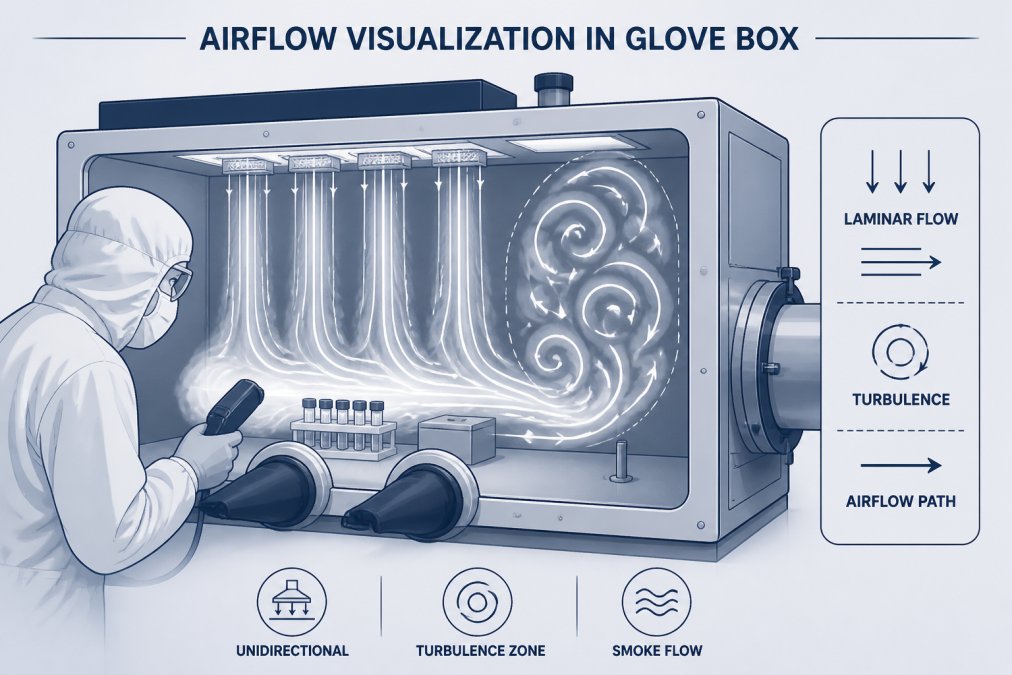
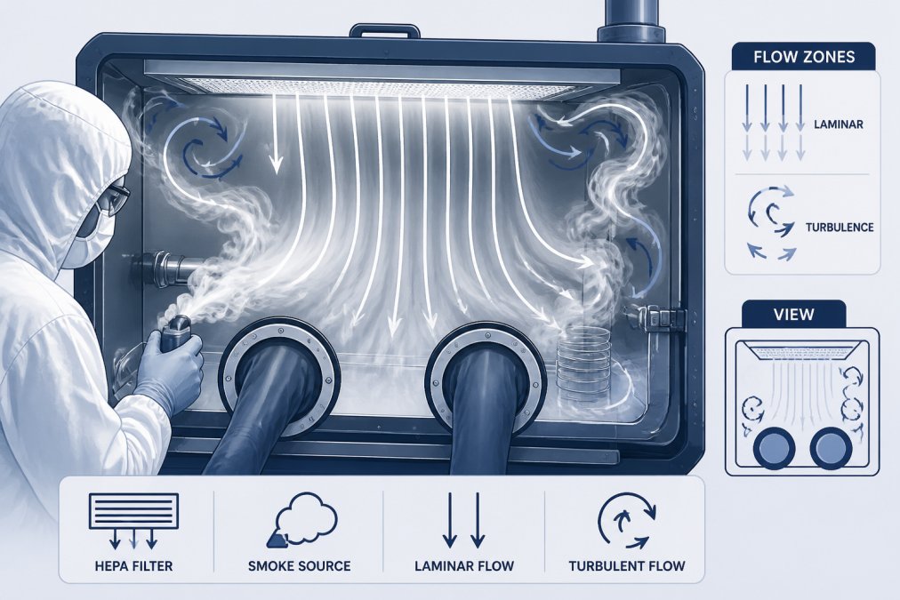
Airflow visualization works by introducing visible fog into your glove box and observing how it moves. What you see tells you whether air flows in predictable laminar patterns or breaks into chaotic turbulence. Turbulent zones can trap particles and create dead spots where contamination accumulates.
Laminar Flow vs. Turbulence Detection
Laminar flow is unidirectional, smooth air movement where particles follow parallel paths without mixing. Air enters from HEPA-filtered supply points, flows across your work surface in a uniform sheet, and exits through exhaust vents. When you introduce fog under laminar conditions, it moves in straight, predictable streams with minimal dispersal.
Turbulence occurs when air currents collide, reverse direction, or encounter obstacles. Vortices form, visible as fog spiraling in tight circles, and dead zones emerge where air barely moves. These zones harbor airborne particles that should have been swept away. In laminar conditions, fog moves smoothly and exits cleanly; under turbulent conditions, fog stalls, swirls, and pools in corners.
Pressure Differential and Containment Integrity
Pressure differential, the slight positive or negative air pressure inside the glove box relative to the surrounding room, is critical for containment integrity. A positive differential prevents external air from leaking in; a negative differential prevents hazardous material from leaking out.
Fog visualization reveals pressure problems indirectly. If fog is sucked toward a glove port or seam, pressure is negative at that point, indicating a leak site. If fog is pushed outward, pressure is positive. By watching fog behavior around all seams, glove ports, and access points, you can confirm that pressure differentials are maintained and containment is intact. This is why smoke studies are mandated by USP 797 and ISO 14644-3.
USP 797 Airflow Visualization Requirements for Compounding Pharmacies
USP 797 requires that all ISO Class 5 environments, including compounding isolators and glove boxes, undergo initial airflow visualization testing and periodic re-testing. The standard mandates that you document laminar flow, verify the absence of turbulence in critical zones, and confirm pressure differentials.
Specifically, USP 797 requires:
- Initial airflow visualization study before the facility operates
- Annual re-qualification or whenever the isolator is relocated, serviced, or modified
- Visual confirmation of unidirectional airflow across the work surface
- Photographic or video documentation of fog behavior
- Written report confirming compliance with flow patterns
The regulation does not prescribe a specific fogger type, but it requires that the fog be visible, controllable, and leave no residue. Liquid nitrogen fogging, while effective, leaves water droplets that can contaminate your work surface and gloves. Ultrasonic piezo foggers using deionized water produce zero-residue fog, making them the preferred choice for USP 797 environments.
Applied Physics supports compounding pharmacies with cleanroom foggers specifically designed for these requirements, generating consistent fog density and operating quietly enough not to disrupt laminar flow patterns during testing.
ISO 14644-3 Smoke Study Protocols and Glove Box Testing
ISO 14644-3 is the international standard for cleanroom testing and classification. Part 3 specifically covers airflow visualization and particle counting methods, defining how to conduct smoke studies, what constitutes acceptable airflow patterns, and how to document results for regulatory compliance.
Cleanroom Certification and Air Exchange Rates
ISO 14644-3 requires that smoke studies be performed with visible fog of consistent density, observable air velocity and direction throughout the test, and recorded results (video or photographs) for regulatory review.
Air exchange rate, how many times per hour the entire volume of air in the glove box is replaced, affects how quickly fog clears after testing. A glove box with 20 air changes per hour (ACH) will clear fog much faster than one with 10 ACH. The cleanroom fogger you select must produce fog that remains visible for the duration of your study (typically 5-10 minutes) without overwhelming the workspace. Portable ultrasonic units from Applied Physics are calibrated to deliver this balance, making them suitable for glove boxes with varying air exchange rates.
Cleanroom Fogger Residue Testing and Zero-Residue Standards
One of the most overlooked aspects of fogger selection is what happens after the fog clears. Liquid nitrogen fogging produces visible fog but leaves behind water droplets and mineral deposits that contaminate glove surfaces, work trays, and product contact areas. In a compounding pharmacy, this forces you to clean and re-validate the entire glove box before resuming operations.
Zero-residue fogging means the fog evaporates completely, leaving no liquid droplets, mineral deposits, or chemical residue. This is achieved using ultrasonic piezo technology with deionized (DI) water or water-for-injection (WFI) water. The ultrasonic transducer vibrates at megasonic frequencies, breaking water into submicron particles that evaporate rather than condense.
Zero-residue fogging is not just a convenience; it’s a compliance requirement in many pharmaceutical settings. If your fog leaves deposits, you must clean and re-validate before resuming compounding, downtime that often runs 2-4 hours, making residue-producing methods economically impractical.
Applied Physics cleanroom foggers use ultrasonic piezo technology that produces zero-residue fog, allowing you to resume operations within minutes, not hours.
Ultrasonic Piezo Technology vs. Liquid Nitrogen Fogging
Two primary technologies compete in the cleanroom fogger market: ultrasonic piezo and liquid nitrogen (LN2) cold fogging.
Ultrasonic Piezo Fogging:
- Mechanism: A piezoelectric transducer vibrates at 128 kHz, breaking water into submicron particles
- Fog output: Consistent, adjustable, and visible
- Residue: Zero residue when using DI or WFI water
- Setup: Plug-in or battery-powered; fills from a water reservoir
- Cost: Lower capital cost; consumables are water only
- Noise: Quiet operation (does not disrupt laminar flow during testing)
- Limitations: Requires clean water supply; cannot be used with chemical additives
Liquid Nitrogen Cold Fogging:
- Mechanism: Liquid nitrogen rapidly evaporates, creating visible fog through thermal expansion
- Fog output: High volume, dramatic visual effect
- Residue: Water droplets and mineral deposits left behind
- Setup: Requires LN2 supply, specialized handling, safety equipment
- Cost: Higher operational cost (LN2 supply and handling)
- Safety: Requires training; risk of cryogenic burns and asphyxiation
- Advantages: Works in any environment; no water quality dependency
For glove box validation in pharmaceutical settings, ultrasonic piezo is the standard choice. It produces clean, zero-residue fog that allows immediate post-study operations.
Fog Density, Visibility, and Deionized Water Requirements
Fog density determines visibility and persistence in the glove box. The ideal fog density for glove box work is one where you can see individual airflow patterns without overwhelming the workspace. This typically requires fog output in the range of 0.26 to 0.89 cubic meters per minute (9 to 31 cubic feet per minute), depending on glove box volume and air exchange rate.
Deionized water is essential for ultrasonic piezo fogging. Tap water contains minerals and ions that can leave deposits on glove surfaces and equipment. DI water has been stripped of these contaminants, producing pure fog that evaporates cleanly. Some applications require WFI (water-for-injection) grade water, which meets pharmaceutical standards for purity.
The Applied Physics CRF2 and CRF4 cleanroom foggers both use DI or WFI water, producing zero-residue fog suitable for pharmaceutical environments. The CRF2 generates 0.26 cubic meters per minute (ideal for small glove boxes), while the CRF4 produces 0.89 cubic meters per minute (suitable for larger isolators).
Portable vs. Fixed Fogger Systems for Pharmaceutical Barrier Isolators
Cleanroom foggers come in two deployment models: portable units that you move between isolators, and fixed systems permanently installed in a single location.
Portable Fogger Systems:
- Advantages: Single unit serves multiple glove boxes; lower capital cost; flexible scheduling
- Disadvantages: Setup/teardown time; potential for cross-contamination if not properly decontaminated between uses
- Best for: Facilities with multiple glove boxes that undergo validation on rotating schedules
Fixed Fogger Systems:
- Advantages: Permanently integrated; minimal setup time; consistent performance; no cross-contamination risk
- Disadvantages: Higher capital cost; dedicated to a single isolator
- Best for: Large-scale pharmaceutical manufacturing; critical isolators that require frequent re-validation
For most compounding pharmacies and smaller manufacturers, a portable ultrasonic fogger is the practical choice. Applied Physics offers portable units (CRF2 and CRF4) that can be moved between isolators and stored between uses.
| Fogger Type | Portability | Setup Time | Residue | Best For |
|---|---|---|---|---|
| Portable Ultrasonic | High (cart-mounted) | 2-3 minutes | Zero | Multiple glove boxes, rotating validation schedules |
| Fixed Ultrasonic | None (permanently installed) | <1 minute | Zero | Single critical isolator, frequent re-validation |
| Portable LN2 | Medium (requires supply cart) | 5-10 minutes | Residue present | Large-scale fabs, high-volume testing |
| Handheld Glycol Fogger | Very high (handheld) | 1 minute | Minimal | Spot checks, small glove boxes |
Troubleshooting Airflow Patterns and Common Validation Failures
Airflow visualization studies often reveal unexpected patterns that require interpretation and corrective action. A systematic diagnostic approach prevents misdiagnosis and unnecessary equipment modifications.
Diagnostic Framework: Fogger Performance vs. Glove Box Design Issues
Before concluding that your glove box has failed validation, confirm that the fogger itself is performing correctly. Weak or inconsistent fog output can create false failure patterns.
Step 1: Verify Fogger Output
Run the fogger in open air for 30 seconds and observe fog density and consistency. The fog should be visible at a distance of 3-5 feet and maintain consistent density throughout the test. If fog is weak, intermittent, or dissipates rapidly:
- Weak fog output: Water reservoir may be empty or water quality degraded. Refill with fresh deionized water and test again.
- Intermittent fog: Ultrasonic transducer may have mineral deposits. Clean the transducer by soaking in distilled water or a 1:1 vinegar-water mixture for 10-15 minutes, then rinsing thoroughly.
- Fog dissipates too quickly: Ambient humidity may be very high (>80%), causing faster evaporation. This is environmental, not a fogger fault.
Step 2: Assess Environmental Conditions
Temperature, humidity, and air exchange rate all affect how fog behaves:
- Temperature: Ultrasonic fog is most visible between 65°F and 75°F. Below 60°F, fog may condense prematurely; above 80°F, it evaporates faster.
- Humidity: Relative humidity below 30% causes fog to evaporate rapidly; above 80% causes condensation. Ideal testing occurs at 40-60% RH.
- Air exchange rate: Verify the design air exchange rate before testing. If fog clears in less than 2 minutes, air exchange rate may be higher than expected.
Step 3: Operator Technique
How you introduce the fog affects what you observe:
- Fogger position: Position the fogger at the supply-air entry point (top or side of the glove box). If positioned at the exhaust, fog will be immediately pulled out.
- Fog introduction rate: Introduce fog gradually over 10-15 seconds, not all at once.
- Observation distance: Stand back 12-18 inches from the glove box window.
- Lighting: Ensure adequate lighting on the glove box interior. Use a bright LED work light if needed.
If you correct operator technique and re-test, many apparent failures resolve.
Common Failure Patterns: Root Cause Analysis
Pattern 1: Vortex (Spiral or Swirling Fog) in the Work Zone
A visible spiral indicates a rotating air current, typically occurring when supply air hits an obstacle and bounces back.
Likely causes:
- Hands or work tray positioned in the direct path of supply air
- Supply diffuser is misaligned or produces a jet rather than a sheet of air
- Exhaust vent is positioned too close to the supply, creating a short-circuit path
Corrective actions:
- Repeat the smoke study with the work area clear. If the vortex disappears, the cause is an obstacle in the airstream.
- If caused by supply diffuser: Reposition the diffuser or install a baffle to spread supply air more evenly.
- If caused by exhaust positioning: Reposition the exhaust vent or install baffles to prevent short-circuiting.
Pattern 2: Dead Zone (Stagnant Fog) at the Back Corner or Side
Fog enters the glove box but doesn’t reach a specific area; it pools or stagnates there instead of being swept toward the exhaust.
Likely causes:
- Exhaust vent is blocked or partially obstructed
- Exhaust vent is undersized relative to the glove box volume
- Supply air is not distributed evenly across the work surface
- Air exchange rate is lower than design specification
Corrective actions:
- Check and clean the exhaust vent. Remove any dust, tape, or debris.
- Verify air exchange rate by consulting the glove box design specifications or conducting an air velocity measurement at the exhaust vent using an anemometer.
- Reposition internal obstacles or install diffusers to distribute supply air more evenly.
Pattern 3: Fog Exits Prematurely at One Point (Localized High-Velocity Zone)
Fog is rapidly pulled toward a single exhaust vent or point rather than flowing uniformly across the work surface.
Likely causes:
- Exhaust vent is oversized or positioned too close to the work surface
- Multiple exhaust vents are present but only one is functioning
- Flexible exhaust ducting is kinked or partially collapsed
Corrective actions:
- Install baffles or diffusers at the exhaust vent to distribute air more evenly.
- Inspect flexible ducting for kinks or collapse. Replace if damaged.
- Verify that all exhaust vents are open and unobstructed.
Pattern 4: Fog Leakage at Seams, Glove Ports, or Access Points
Fog is visible being pulled out through a seam, glove port, or access point rather than through the intended exhaust vent.
Likely causes:
- Glove port seal is degraded or improperly installed
- Access door is not fully sealed
- Seam or weld has a crack or gap
- Glove box is operating at negative pressure
Corrective actions:
- If the leak is at a glove port, inspect the glove for tears or the port seal for degradation. Replace the glove or reseal the port.
- If the leak is at an access door, ensure the door is fully closed and latched. Check the door gasket for damage.
- If the leak is at a seam or weld, the glove box may require professional repair.
- Document the leak location and size in your validation report.
Documentation and Corrective Action Workflow
Always record your smoke study on video. Review the footage frame-by-frame to identify exactly where airflow breaks down. Still photographs from multiple angles also help.
Documentation checklist:
- Date, time, and operator name
- Glove box model and serial number
- Fogger model and serial number
- Ambient temperature and humidity
- Video recording of the entire 5-10 minute test
- Still photographs from at least three angles
- Written observations of any vortices, dead zones, or leaks
- Pass/fail determination
- If failed, description of corrective actions taken
- Date and results of re-test after corrective actions
If your glove box fails validation, do not resume operations until corrective actions are complete and a re-test confirms compliance.
Calibration and Validation Protocols for Glove Box Foggers
Your cleanroom fogger itself must be calibrated and validated to ensure it’s producing consistent, reliable fog output. Regulatory auditors expect documented evidence that the fogger has been verified before use. For compounding pharmacies operating under USP 797, state pharmacy boards and the FDA expect to see calibration records as part of your quality assurance documentation.
Fogger Calibration Requirements and Acceptance Criteria
Calibration means verifying that the fogger produces the specified output and that output remains consistent over time.
1. Fog Output Verification
Confirm that the fogger produces the specified volume of fog, typically measured in cubic meters per minute (m³/min) or cubic feet per minute (CFM).
Acceptance criteria:
- Fog output must be within ±10% of the manufacturer’s specification
- Fog output must be consistent throughout a 10-minute test (no more than ±5% variation between the first and last minute)
How to measure:
Direct the fogger into a calibrated chamber of known volume and measure the time required to fill it with visible fog. Calculate volume per minute. Repeat three times and average the results. Many cleanroom service companies offer fogger calibration as a service.
Frequency:
- Initial calibration before first use
- Annual calibration thereafter, or more frequently if the fogger is used more than twice per week
- Calibration after any service or repair
2. Water Quality Verification
Verify that you’re using the correct grade of water. Ultrasonic foggers require deionized (DI) water or water-for-injection (WFI) grade water.
Acceptance criteria:
- Conductivity must be ≤10 microsiemens per centimeter (µS/cm) for DI water
- Conductivity must be ≤1.3 µS/cm for WFI water (pharmaceutical grade)
- pH must be between 5.5 and 8.0
How to measure:
Use a conductivity meter to test your water supply. Test the water before filling the fogger reservoir.
Frequency:
- Test water quality before each validation study
- If you use a centralized DI water system, test the system output monthly
- If you purchase bottled DI water, test each new bottle when it arrives
3. Ultrasonic Transducer Inspection and Cleaning
For ultrasonic foggers, the piezoelectric transducer is the heart of the system. A degraded or dirty transducer produces weak or inconsistent fog.
Inspection criteria:
- Transducer surface should be clean and free of mineral deposits
- Transducer should vibrate visibly when powered on
- Transducer should produce fog within 2-3 seconds of being powered on
How to clean:
- Unplug the fogger and allow it to cool for 5 minutes
- Remove the water reservoir
- Inspect the transducer surface for white or brown deposits
- If deposits are visible, soak in distilled water or a 1:1 vinegar-water mixture for 10-15 minutes
- Gently scrub with a soft brush (do not use abrasive materials)
- Rinse thoroughly with distilled water and air dry completely
- Test the fogger in open air to confirm fog output is restored
Frequency:
- Inspect transducer visually before each use
- Clean if deposits are visible or if fog output is weak
- Deep cleaning monthly if the fogger is used weekly
4. Functional Test Before Each Validation Study
Before conducting a validation study, run the fogger for 30 seconds in a neutral area and confirm that fog is visible and consistent.
Acceptance criteria:
- Fog should be visible at a distance of 3-5 feet
- Fog should be consistent throughout the 30-second test
- Fog should disperse naturally (not condense into droplets)
If fog output is weak or erratic:
- Do not proceed with validation
- Check water level in the reservoir
- Check water quality (conductivity)
- Clean the transducer
- Re-test in open air before attempting validation again
Validation Protocol: Step-by-Step Procedure
Validation is the process of using the fogger to test your glove box’s airflow patterns. A proper validation study takes 20-30 minutes from start to finish and produces documented evidence of compliance.
Pre-Test Preparation (10 minutes)
-
Verify glove box operation: Ensure the glove box has been operating normally for at least 30 minutes. Do not conduct a validation study immediately after the glove box is powered on or after maintenance work.
-
Verify environmental conditions: Record ambient temperature and relative humidity. Ideal testing occurs at 65-75°F and 40-60% RH.
-
Prepare the fogger: Fill the water reservoir with fresh DI or WFI water. Verify water quality with a conductivity meter if required. Plug in the fogger and allow it to warm up for 2-3 minutes.
-
Prepare documentation: Set up a video camera or smartphone to record the entire test. Position the camera so it captures the full interior of the glove box. Prepare a written log with date, time, operator name, glove box model, and fogger model.
-
Functional test: Run the fogger in open air for 30 seconds and confirm fog output is visible and consistent.
Fog Introduction and Observation (10 minutes)
-
Position the fogger: Place the fogger at the supply-air entry point of the glove box (typically the top or side). Do not position the fogger at the exhaust vent.
-
Start recording: Begin video recording before introducing fog.
-
Introduce fog gradually: Activate the fogger and introduce fog over 10-15 seconds. Allow the fog to fill the glove box gradually so you can observe airflow patterns clearly.
-
Observe for 5-10 minutes: Watch the fog movement carefully. Observe whether fog flows smoothly across the work surface (laminar flow) or swirls and stagnates (turbulence), whether fog reaches all areas or pools in dead zones, and whether fog is pulled toward the exhaust vent uniformly or sucked toward one point.
-
Take still photographs: Capture photographs from at least three angles showing fog distribution at different points in the test.
-
Turn off the fogger: After 5-10 minutes, turn off the fogger and allow fog to clear completely.
Post-Test Analysis (10 minutes)
-
Review video footage: Play back the video and review frame-by-frame. Identify any vortices, dead zones, or unexpected patterns.
-
Determine pass/fail: Based on your observations, determine whether the glove box passes or fails validation. Acceptance criteria typically include laminar flow across the work surface, no vortices or turbulent zones in critical work areas, no dead zones where fog stagnates, uniform fog clearance, and maintained pressure differential.
-
Generate a written report: Document your findings in a formal validation report including date, time, and operator name; glove box model, serial number, and location; fogger model, serial number, and calibration date; ambient temperature and humidity; water type and quality; video file name and location; photographs; observations of airflow patterns; pass/fail determination; and if failed, recommended corrective actions.
Regulatory Compliance and Audit Readiness
For compounding pharmacies, state pharmacy boards and the FDA expect to see validation reports as part of your quality assurance documentation.
What auditors look for:
-
Calibration records: Evidence that the fogger was calibrated before first use and at regular intervals thereafter.
-
Validation reports: Complete documentation of each validation study, including video or photographs, written observations, and pass/fail determination.
-
Corrective action documentation: If a glove box failed validation, auditors expect to see documentation of the corrective actions taken, the date of re-testing, and the results of the re-test.
-
Maintenance records: For portable foggers, auditors expect to see records of cleaning, transducer inspection, and water quality verification.
-
Training records: Auditors may ask to see evidence that operators have been trained on proper fogger use and validation procedures.
Record retention:
Retain validation reports and calibration records for at least 3 years (or longer if required by your state pharmacy board or company policy). Store records in a secure location, either in a physical binder or in a digital system with access controls.
Regulatory references:
- USP 797: Requires initial airflow visualization study and periodic re-testing. Annual re-qualification is standard practice.
- USP 800: Hazardous drug handling; requires validation of negative-pressure containment devices.
- ISO 14644-3: International standard for cleanroom testing. Specifies that smoke studies must be conducted and documented.
- FDA Guidance on Aseptic Processing: Recommends validation of airflow patterns in aseptic processing areas.
Maintenance and Sanitization Between Uses
If you use a portable fogger across multiple glove boxes, you must sanitize the fogger between uses to prevent cross-contamination.
Sanitization procedure:
- Empty the water reservoir completely
- Rinse the reservoir with distilled water
- Wipe the exterior of the fogger with a lint-free cloth dampened with 70% isopropyl alcohol
- Allow the fogger to air dry completely before moving to the next glove box
- Fill the reservoir with fresh DI water before use in the next glove box
This procedure takes 5-10 minutes and prevents contamination from one glove box to the next.
Frequently Asked Questions
Why is airflow visualization required for glove boxes?
Airflow visualization using a cleanroom fogger reveals whether laminar flow patterns are intact and identifies turbulence zones or dead spots where particulate contamination can accumulate. For pharmaceutical barrier isolators and compounding pharmacies under USP 797 regulations, this smoke study proves containment integrity and cross-contamination prevention. Without visual confirmation, you cannot certify that your glove box meets ISO 5 cleanroom standards or pass GMP audits.
Do cleanroom foggers leave residue in glove boxes?
Ultrasonic cleanroom foggers using deionized or WFI water produce zero-residue fog that leaves no deposits. Liquid nitrogen or glycol-based foggers may leave trace residue requiring post-validation cleaning. Applied Physics CRF2 and CRF4 models use DI water exclusively, ensuring your glove box remains contaminant-free and compliant with USP 797 and ISO 14644-3 smoke study protocols.
How do you perform an airflow visualization test in a glove box?
Start by sealing the glove box and setting it to normal operating pressure. Activate your cleanroom fogger at low fog density near the inlet to observe laminar flow patterns. Move the nozzle systematically across work surfaces, glove ports, and exhaust areas, watching for vortices or turbulence. Document any airflow anomalies with photographs or video. The fog should move smoothly without pooling or reversing direction. This ISO 14644-3 smoke study validates your glove box's containment integrity and confirms compliance.
