1 · Geometry
- Room, RABS, isolator, BSC or hood
- Approximate dimensions / volume
- Fog injection point and critical zone
- Required visible travel distance

Use this matrix as a starting point. Product selection should follow the current quoted configuration and the actual study geometry; restrictive delivery paths should never be sized from a room-volume or free-air figure alone.
| Model | Technology | Best starting point | Selection status / fact |
|---|---|---|---|
| CRF2 | Ultrasonic | Localized studies, hoods, small enclosures | Compact current CRF platform; confirm the quoted product sheet. |
| CRF3 | Ultrasonic | Mid-range cleanroom / enclosure studies | Mid-range current CRF platform; confirm the quoted product sheet. |
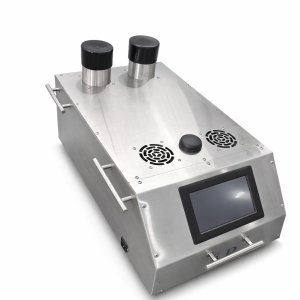
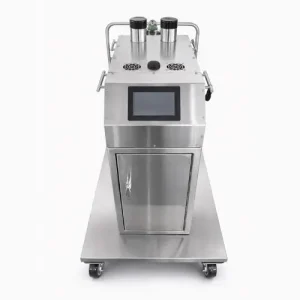
| CRF6 | Ultrasonic | Higher-output portable ultrasonic studies | 48 piezos · dual 80 mm outlets · ≈2.4 m³/min · 7-inch HD display. |
| AP35 | LN₂ · passive/dewar | 35 L passive/dewar AP Series option | Current passive/dewar architecture. |
| AP30 | LN₂ · self-pressurized | Compact self-pressurized AP Series option | Current self-pressurized architecture; not a replacement for AP35. |
| AP50 | LN₂ · self-pressurized | Intermediate self-pressurized AP Series option | Current self-pressurized platform; confirm quoted performance. |
| AP95 | LN₂ · passive/dewar | Higher-capacity passive/dewar AP option | Current passive/dewar platform; confirm quoted performance. |
| AP175 | LN₂ · passive/dewar | Largest passive/dewar AP Series option | Current passive/dewar platform; confirm quoted performance. |
| AP100 | LN₂ · self-pressurized | Higher-capacity self-pressurized AP option | Current self-pressurized platform. |
| AP200 | LN₂ · self-pressurized | Largest self-pressurized AP Series option | Current self-pressurized platform for larger-scale planning. |
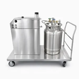
AP Series LN₂ foggers are offered in two current architecture families. Self-pressurized models include AP30, AP50, AP100 and AP200. Passive/dewar-style models include AP35, AP95 and AP175. Choose the architecture from the application, handling preference, study duration and fog-delivery path rather than treating one architecture as the successor to the other.
Hose length, diameter, bends, Y/T adapters, a restrictive injection port and enclosure pressure can all reduce or redistribute the fog that actually reaches the test area. For isolators and RABS, evaluate the intended delivery path under representative pressure conditions.
The quote should identify the actual application, enclosure/room dimensions, pressure relationship, hose/port geometry and study objective so Applied Physics can recommend the appropriate configuration.
Room or enclosure volume is useful context, but it does not describe the resistance between the fogger and the point where the tracer must be visible. The sizing decision should capture the complete delivery path and the evidence the study needs to produce.
Hose length, diameter, bends, Y/T adapters, a restrictive injection port and enclosure pressure can all reduce or redistribute the fog that actually reaches the test area. For isolators and RABS, evaluate the intended delivery path under representative pressure conditions.
Combining two fogger outlets through a reverse Y into a single downstream hose can add restriction and backpressure. Where practical, preserve separate delivery paths or use a manifold/downstream line sized for the combined flow. If a combined line is required, validate that exact hose and enclosure configuration before the formal study.
The same fogger can behave very differently depending on how the fog is delivered. The accessory plan should support visibility without creating a tracer jet that overpowers the airflow being observed.
Use the shortest practical route and avoid unnecessary reductions. Long flexible runs and small downstream diameters increase resistance.
Use a wand, curtain or diffuser when the study needs fog distributed across a wider region or introduced at lower local momentum.
Use splitters to serve multiple injection points only after considering the resulting balance and restriction. Valved branches can help tune the distribution.
Choose the study environment first, then confirm tracer technology, delivery path and runtime.
Showing all 9 resultsSorted by latest

A fogger selected to reveal airflow is not automatically the correct system for distributing sterilant chemistry. Start with the process objective, then select the technology and delivery configuration.
CRF ultrasonic and AP Series LN₂ systems generate visible tracer for cleanroom smoke studies, hoods, RABS, isolators and other controlled-environment airflow evaluations.
CRF-S and related decontamination systems distribute site-approved chemistry. Chemical compatibility, room conditions, cycle design, contact requirements and validation remain application-specific.
Hose diameter, length, bends, port restriction, outlet configuration, pressure differential, wand design and lighting can determine whether the tracer is visible where it matters.
Equipment supports the study or process. The applicable protocol, quality system, facility controls and executed validation determine acceptance.

Enter your details below to save your shopping cart for later. And, who knows, maybe we will even send you a sweet discount code :)
Allow notifications to get real-time updates about your shopping cart and who knows, you may even receive a sweet discount code 😊