
Last Updated: October 4, 2026
Cleanroom airflow testing is the practice of measuring how air moves through a controlled space to confirm it meets its classification and compliance requirements. Getting the scope right before you touch a single instrument saves hours later. This guide walks through the full sequence we recommend, from scope definition to final report.
Start by writing down four things:
That last point matters more than most teams admit. A sterile compounding pharmacy under USP 797 has different acceptance criteria than a semiconductor fab chasing ISO Class 5. If you skip this step, you will run tests that look fine but fail an audit.
Watch Out Testing without a written scope is the most common audit finding we see. If your protocol does not name the room class and operating state, your results cannot be judged pass or fail, and the whole test is wasted.
Preparation is where good airflow testing is won or lost. Before any instrument comes out of its case, review the room’s design and installation records against what is actually built.
Pull these documents:
Then walk the room. Check that filters are seated, diffusers match the drawings, and nothing has been added since the last test. A new piece of equipment or a moved bench changes airflow, and your baseline is now wrong.
A common mistake is treating the walkthrough as a formality. In practice, it catches problems that would otherwise show up as failed tests hours later.
The right cleanroom airflow test equipment depends on what you are measuring. Most jobs need four tools: an anemometer for velocity, a smoke generator for pattern visualization, a photometer for filter integrity, and a particle counter for air quality.
Lighthouse Worldwide Solutions
| Test | Instrument | What It Confirms |
|---|---|---|
| Air velocity | Anemometer | Supply air speed at filter face |
| Airflow pattern | Smoke generator | Direction and uniformity |
| Filter integrity | Aerosol photometer | No leaks in HEPA media or seals |
| Particle count | Particle counter | Room meets its ISO class |
Calibrate every instrument before the test and record the certificate number. An out-of-calibration anemometer invalidates your velocity data, no matter how careful the technician was.
For particle work at the smallest sizes, a handheld condensation particle counter detects particles down to 0.01 micrometers, which matters when your process demands sub-10nm sensitivity. Applied Physics supplies the Model 3800 for exactly this kind of precision measurement.
Pro Tip Log calibration dates on the same sheet as your test data. When an auditor asks to trace a result, you will have the instrument, the certificate, and the reading in one place.
Air velocity and air changes per hour (ACH) are the two numbers that tell you whether supply air is strong enough to sweep particles out of the room and dilute whatever the process generates. They are related but not interchangeable: velocity describes local speed at the filter face, while ACH describes how many times the entire room volume is replaced in an hour. A room can pass one and fail the other, so measure both.
Velocity readings at a HEPA filter face are typically taken with one of three instruments, and the choice changes your numbers:
For unidirectional (laminar) zones, most protocols call for a velocity at the filter face in the range your design specifies, commonly around 0.3 to 0.5 meters per second (roughly 60 to 100 feet per minute), but the governing standard and your approved protocol set the actual limit. Do not assume a number; read it from the design specification.
A single center reading hides edge dead zones. Use a grid:
For a non-unidirectional room, you are usually measuring supply diffusers rather than a full filter face, so take readings across the diffuser throat or use a capture hood to get total flow per outlet.
ACH is total supply airflow divided by room volume, expressed per hour:
The result is ACH. Compare it to the target for your room’s class and operating state. A common pattern is that ISO Class 5 and cleaner spaces require far higher ACH than ISO Class 7 or 8, and USP 797/800 compounding areas carry their own minimums, but the number that governs your test is the one in your approved protocol, not a rule of thumb.
An out-of-calibration anemometer invalidates the data no matter how careful the technician was. Before the test:
Compare each measurement against the acceptance criteria you wrote in Step 1, the room class, the operating state (at-rest or in operation), and the governing standard. A velocity that passes at-rest can fail in operation once equipment and personnel are in place, so confirm which state your protocol requires before you judge the result. If velocity passes but ACH is short, the total supply volume is the problem, not the filter face; check for closed dampers, reduced FFU speed, or duct imbalance.
A cleanroom smoke study uses visible smoke or vapor to show how air actually moves through the space. It is the fastest way to catch turbulence, dead zones, and reversed flow that numbers alone will miss.
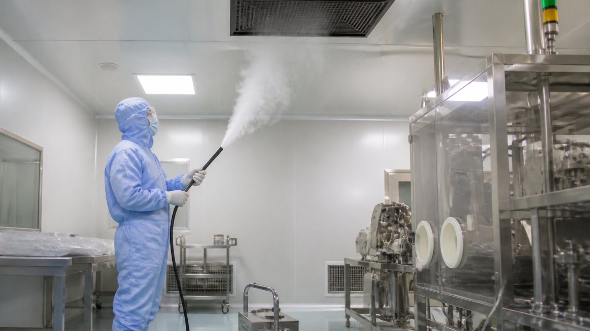
A technician in full cleanroom gowning holding a fogger wand, releasing visible white smoke to visualize unidirectional airflow from a ceiling HEPA filter in a pharmaceutical cleanroom
Introduce smoke upstream of the filter and watch where it goes. In a well-designed unidirectional room, the smoke should travel in a straight, parallel path from ceiling to floor. Any curling, backflow, or stalled pockets signal a problem.
Applied Physics has built cleanroom foggers since 1992, offering both LN2 ultrapure and ultrasonic units.
Watch Out Smoke studies get misused when operators chase dramatic visuals instead of testing the actual airflow path. A swirling cloud looks impressive but tells you nothing if it is not released at the right point.
These are two separate tests with two separate purposes. Integrity testing proves the filter itself is not leaking. Particle counting proves the room as a whole meets its class. Run integrity first, there is no point counting particles in a room with a known filter leak.
Integrity testing challenges the filter with an aerosol and scans the downstream face for any aerosol that gets through. The two standard challenge aerosols are PAO (poly-alpha-olefin) and DOP (dioctyl phthalate); PAO is the more common choice today because of health and handling considerations. Your protocol will name which one to use.
Setup and execution:
The Aerosol Photometer BAP-350 from Applied Physics handles this scan with a portable probe and automatic upstream/downstream switching, and it meets NSF49, IEST, and ISO 14644 standards.
Watch Out A scan that is too fast is the most common reason a real leak is missed. If you cannot see the probe position change smoothly across the filter face, you are moving too quickly.
After integrity passes, count airborne particles. A particle counter draws room air through a sensor and reports concentration by size channel, typically 0.3, 0.5, and 5.0 micrometers, though the channels your protocol requires depend on the room class.
Sampling plan:
Compare each result to the limit for your room’s class at the correct operating state. If a location exceeds the limit, check filter seating, gowning, and recent activity in the room before assuming the filter failed, a single high reading is often a transient event, not a room defect.
For continuous oversight between formal tests, a cleanroom monitoring system, such as the Cleanroom Monitoring System – Model CRMS, can track particle counts, differential pressure, temperature, and humidity against ISO and GMP requirements.
A filter passes integrity if no scan point exceeds the threshold. A room passes particle counting if every sampled location meets the class limit for the required operating state. Both results belong in the same report as the velocity and ACH data from Step 4, so the room’s performance can be judged as a whole rather than test by test.
Every result needs a clear pass or fail against the room’s classification and operating state. Do not judge on the fly. Use the acceptance criteria you wrote in Step 1.
When a test fails, work through the likely causes:
A failed test is not a dead end. It is data. Fix the cause, retest, and document both.
Documentation is what turns a test into evidence. Record the room, the date, the instruments and calibration numbers, the raw readings, and the pass/fail call for each test.
Build a reusable report template with these fields:
Retesting follows a schedule set by your protocol and the governing standard. Any corrective action triggers a retest of the affected area, not the whole room, unless the fix changes overall airflow.
For teams that want continuous data between formal tests, Applied Physics offers monitoring systems, such as the Cleanroom Monitoring System – Model CRMS, that log particle counts and pressure around the clock.
A cleanroom airflow testing procedure follows a fixed sequence: define the scope and acceptance criteria, complete a pre-test walkthrough and record review, calibrate all instruments, measure air velocity and air changes per hour, run a smoke study to visualize airflow patterns, test HEPA filter integrity and airborne particle counts, then interpret results against ISO 14644 pass/fail limits. Each step is documented so the test is traceable for audits. Skipping preparation or calibration is the most common reason results get rejected during certification.
A cleanroom smoke study uses a fogger to release visible vapor at defined points, such as filter faces, work zones, and doorways. You watch how the smoke travels: unidirectional airflow should move in straight, parallel lines with no turbulence or dead zones. Record the room at its operational condition, since personnel and equipment change airflow. Note any reverse flow, eddies, or smoke that stalls.
Cleanroom airflow test equipment typically includes a thermal anemometer or vane anemometer for velocity, a capture hood for airflow volume at filter faces, an aerosol photometer for HEPA filter leak testing, a particle counter for airborne particle counts, and a fogger for smoke studies. Instrument calibration records matter as much as the tool itself. An out-of-calibration anemometer can shift readings enough to fail a room that is actually compliant, or worse, pass one that is not.
Document each test with the room classification, operating state (at-rest or operational), instrument model and calibration date, measurement locations, raw readings, acceptance criteria, and pass/fail outcome. Include smoke study video or photos with timestamps. Add a corrective action section for any failed point and a retest date. This record set is what auditors review during cleanroom validation and certification, so traceability from raw data to final report should be complete.
Cleanroom airflow testing only holds up when the scope, instruments, and documentation all line up. Applied Physics has supported contamination control since 1992, with cleanroom foggers for airflow visualization, calibration wafer standards, and particle metrology built for GMP and ISO environments. Contact us to match the right equipment to your room class and testing protocol.

Enter your details below to save your shopping cart for later. And, who knows, maybe we will even send you a sweet discount code :)
Allow notifications to get real-time updates about your shopping cart and who knows, you may even receive a sweet discount code 😊