
Computer control makes a reflow oven easier to operate consistently. It allows operators to set heating-zone temperatures, adjust conveyor speed, and review operating records. However, those settings do not prove that every solder joint on a printed circuit board reaches the required temperature.
The AP PC6635 fully computer-controlled lead-free reflow oven lists independently controlled heating zones, temperature-curve testing, and automatic data recording. These features support process control, but a reliable soldering recipe still depends on measuring how the actual assembly heats and cools.
Thermal profiling provides that evidence. It helps manufacturers check whether their oven settings suit the solder paste, PCB construction, and component temperature limits before committing a production batch.
What Does the AP PC6635’s Computer Control Provide?
According to the published specifications, the AP PC6635 includes six upper and six lower heating zones, two cooling zones, a 2,200 mm heating length, and an adjustable conveyor speed of 0–2,000 mm/min. Its listed controls combine an industrial computer with a Siemens PLC. The page also describes temperature-curve records, timestamped alarms, and production reporting.
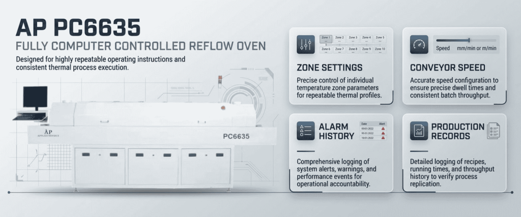
These functions help operators establish and repeat a defined recipe. The limitation is that a controlled oven temperature is not the same as a measured solder-joint temperature.
A component connected to a large copper area may heat more slowly than a small nearby component. Board thickness, component mass, and assembly construction can therefore produce different temperatures across the same PCB.
Oven Recipe vs. Thermal Profile: What Is the Difference?
An oven recipe is the set of operating instructions, including heating-zone temperatures and conveyor speed.
A thermal profile is the measured temperature history of selected locations on an assembly as it travels through the oven. It shows the heating rate, peak temperature, time above the solder alloy’s liquidus temperature, and cooling behavior.
BTU’s technical guidance makes this distinction between the programmed recipe and the temperatures the board actually experiences.
| Process check | What computer control provides | What PCB thermal profiling verifies |
|---|---|---|
| Zone temperatures | Defined heating-zone setpoints | How selected assembly locations respond |
| Conveyor speed | A programmed transport speed | The resulting time-temperature exposure |
| Peak temperature | Oven operating settings | Measured peaks at selected PCB locations |
| Time above liquidus | Settings that influence solder heating | How long measured locations remain above liquidus |
| Thermal variation | Repeatable operating conditions | Temperature differences between monitored locations |
| Production records | Machine status and alarm history | Evidence linking a recipe to an assembly’s thermal response |
Both are necessary: the recipe controls the process, while the profile checks its result.
Why Lead-Free Soldering Needs Careful Profiling
Lead-free soldering can leave a narrower thermal process window, making accurate profiling particularly important. The recipe must provide enough heat for soldering without exceeding the assembly’s temperature limits. Heller’s process guidance emphasizes matching the profile to both the solder paste and the PCB assembly.
Different Areas of a PCB Heat at Different Rates
An oven display cannot establish whether the coldest joint has received sufficient heat while the hottest component remains within its allowable limit.
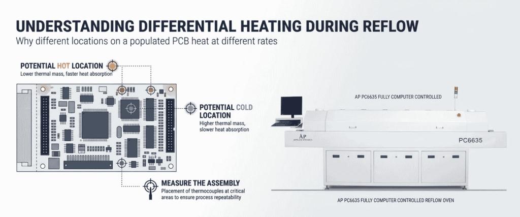
Profiling should therefore include locations that represent different thermal conditions. AIM Solder recommends strategically placed thermocouples on a populated assembly rather than relying on oven settings alone.
Solder Paste Requirements Must Guide the Recipe
There is no single temperature recipe suitable for every lead-free assembly.
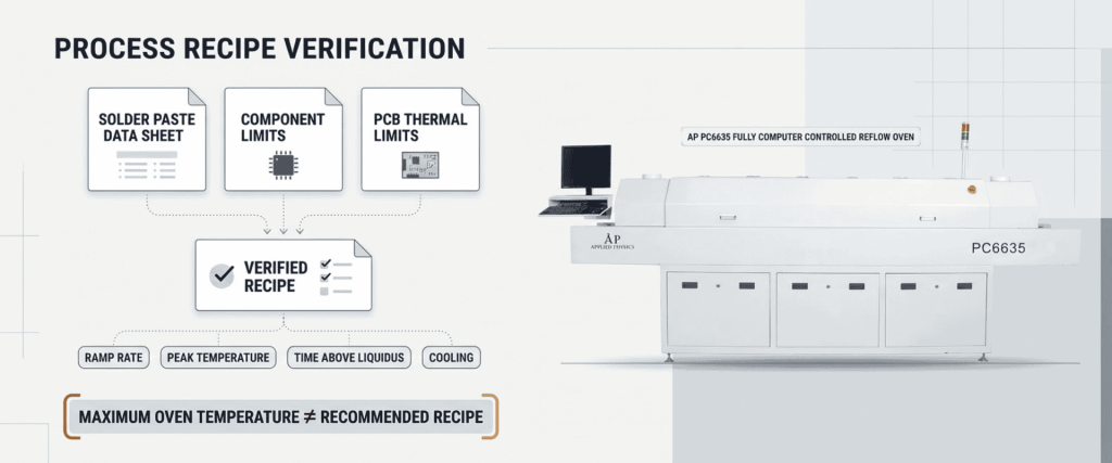
Start with the solder paste supplier’s current technical data sheet, then check component and PCB thermal limits. Use those requirements to evaluate ramp rate, peak temperature, time above liquidus, and cooling behavior.
A published maximum oven temperature is an equipment capability—not a recommended production setting.
Solder Defects Can Have Several Causes
An unsuitable profile can contribute to problems such as poor wetting, voiding, and head-in-pillow defects. However, a defect found after reflow is not automatically an oven problem.
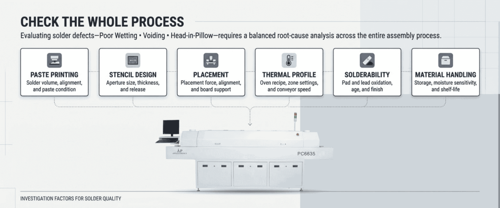
Paste printing, stencil design, placement, solderability, and material handling also affect results. AIM and Heller both describe the importance of evaluating profiling alongside other assembly-process variables.
How to Establish a Thermal Profile for the AP PC6635
1) Define the Assembly’s Process Limits
Before changing oven settings, collect:
- Solder paste profile recommendations.
- Component temperature and exposure limits.
- PCB material and construction details.
- Applicable customer acceptance criteria.
- Requirements for heat-sensitive parts.
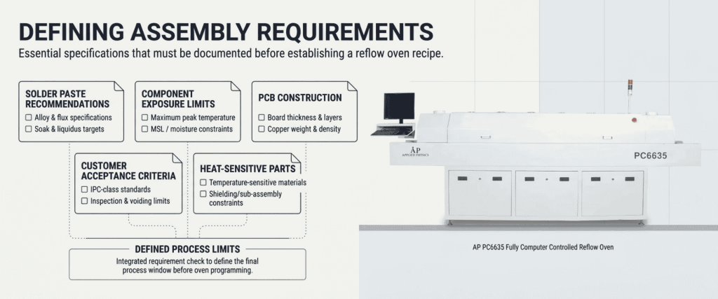
These establish the boundaries against which the measured profile will be assessed.
2) Use a Representative Populated Assembly
A bare PCB does not reproduce the thermal behavior of a fully populated board.
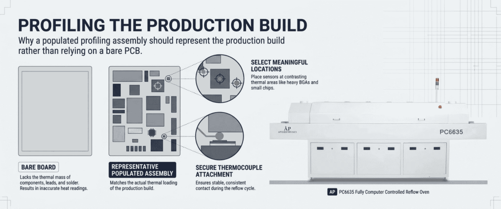
Where practical, use a dedicated profiling assembly that represents the production build. Place thermocouples at locations selected for their thermal significance, including likely hot and cold areas. Attachment quality matters because a poorly secured thermocouple can produce misleading readings.
3) Confirm the Profiling Equipment Is Suitable
The AP PC6635 page lists a standard three-point temperature-curve test configuration. Confirm its operation, sensor arrangement, calibration provisions, and data output before relying on it for a particular assembly.
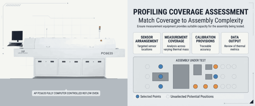
AIM describes an ideal setup using five to seven strategically placed thermocouples. This does not mean every PCB requires that number; measurement coverage should reflect the assembly’s complexity and thermal risks. If the supplied arrangement cannot cover the necessary locations, confirm compatible external profiling options.
4) Run, Measure, and Adjust
After the oven reaches stable operating conditions, run the instrumented assembly and compare its measured profile with the defined limits.
Review:
- Heating ramp rate.
- Peak temperatures at monitored locations.
- Time above liquidus.
- Temperature differences across the assembly.
- Cooling behavior.
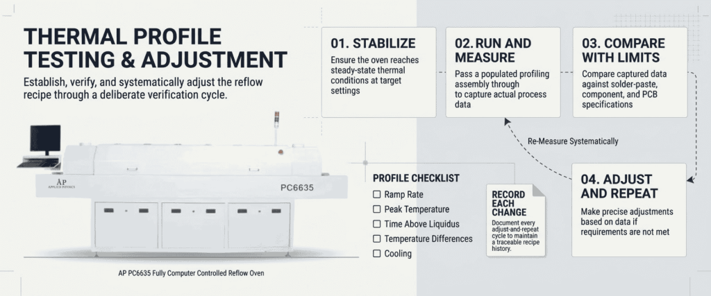
Adjust zone settings or conveyor speed in a controlled manner, record the change, and repeat the measurement. Avoid changing several variables at once without documenting them.
5) Save the Qualified Recipe and Evidence
Retain the recipe alongside the PCB revision, solder paste details, thermocouple locations, profile results, and approval record.
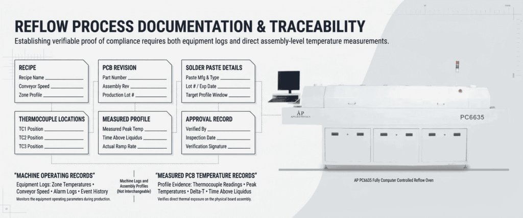
The AP PC6635’s advertised logging functions can support troubleshooting, but confirm which records represent machine conditions and which contain measured PCB temperatures. They are not interchangeable.
When Should You Check the Profile Again?
Reassess the profile when a change could affect heat transfer or process limits, including:
- A new assembly or significant PCB revision.
- A solder paste or alloy change.
- Changes to zone settings or conveyor speed.
- A different carrier or board-support arrangement.
- Maintenance affecting heating, airflow, or transport.
- Unexpected solder defects or evidence of process drift.
Also establish routine verification based on process risk, customer requirements, and the site’s quality procedures.
Oven verification and product profiling serve different purposes. IPC-7801 addresses baseline and periodic verification of oven performance and repeatability; it explicitly distinguishes this from developing or verifying an assembly-specific recipe, directing readers to IPC-7530 for product-profile guidance.
Conclusion
The AP PC6635’s computer control can help operators maintain defined temperatures, conveyor settings, and operating records. Thermal profiling answers a separate question: does that recipe give this PCB assembly the thermal exposure it needs?
Use the published equipment specifications as a starting point, then verify performance with representative assemblies and suitable measurements. Keep the qualified recipe, profile data, and change history together. This provides a sounder basis for repeatable lead-free soldering than relying on the oven display alone.
Frequently Asked Questions (FAQs)
1. Does the AP PC6635 need profiling if its temperature control is accurate?
Yes. Temperature-control accuracy does not establish the temperatures reached at individual solder joints. Profiling measures the assembly’s response.
2. Can one AP PC6635 recipe work for every PCB?
Not without verification. Different board constructions, component populations, and solder pastes may require different recipes.
3. Is the standard three-point test enough for every assembly?
Not necessarily. Confirm whether it covers the assembly’s important thermal locations. More complex boards may need additional measurement coverage.
4. Does thermal profiling eliminate all solder defects?
No. It helps identify thermal-process problems, but printing, placement, materials, and PCB design must also be considered.