
Last Updated: August 15, 2026
Particle metrology testing requires specific equipment, reference materials, and environmental controls to produce reliable, traceable results. Before you begin any measurement campaign, verify that your setup includes the core components: a calibrated particle counter, aerosol generation equipment, reference standards, and a controlled measurement environment.
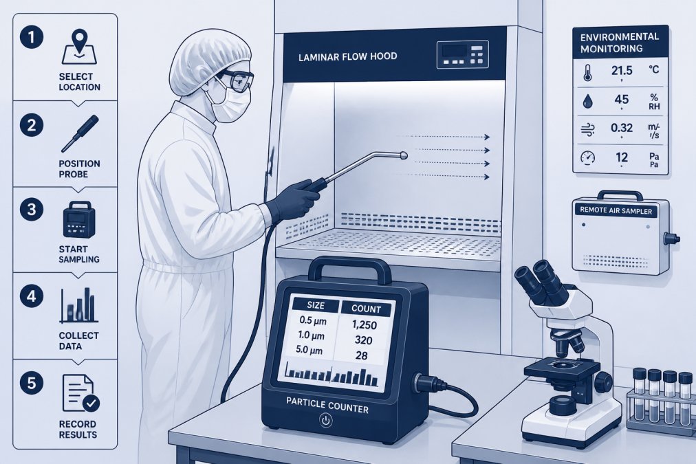
Process diagram showing steps for particle metrology testing
The most critical item is a particle counter capable of detecting particles in the size range relevant to your application. For pharmaceutical cleanrooms under USP 797, you’ll need instruments sensitive to particles as small as 0.5 micrometers. Semiconductor fabs requiring sub-10nm detection demand even higher precision. Your counter must be traceable to a recognized calibration standard, this is non-negotiable for regulatory compliance.
Beyond the counter itself, you’ll need an aerosol generator to create test particles for validation studies. Applied Physics offers both the Aerosol Generator-Cold Type BAG-4B for general cleanroom applications and the Aerosol Generator-Cold Type BAG-6D for pharmaceutical filter leak detection. Cold-type generators produce neutral, uniform aerosol without thermal artifacts that can skew particle size distribution data.
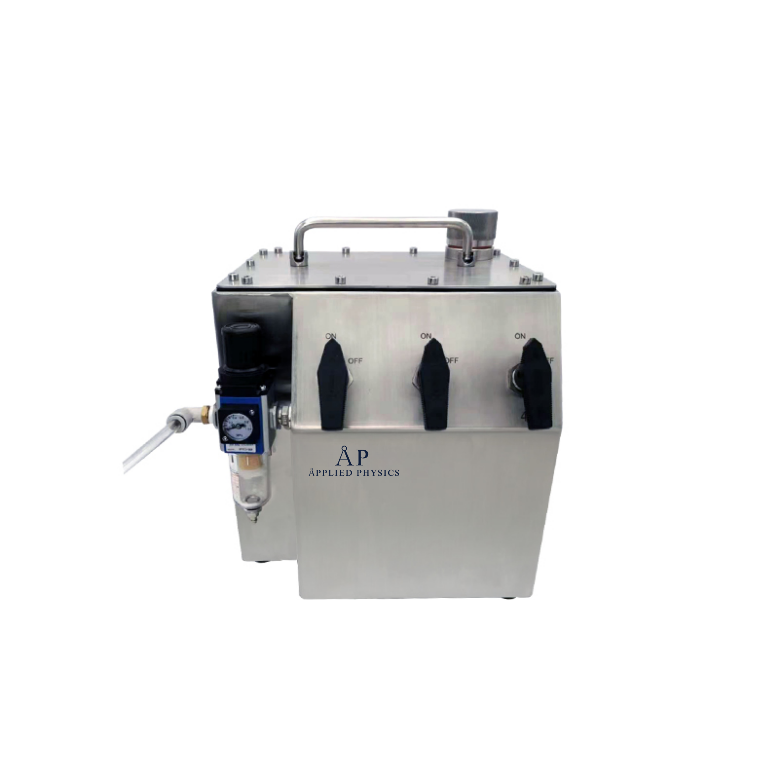
Aerosol Generator-Cold Type BAG-4B
You’ll also need reference standards, typically latex spheres or calibration wafers, to verify your instrument’s signal response and detection limit. These standards must be certified and traceable to NIST or equivalent metrology authority. Environmental monitoring equipment (temperature, humidity, differential pressure sensors) ensures your measurement environment remains stable during testing. Finally, prepare data acquisition software capable of logging particle counts across multiple size channels and calculating geometric standard deviation for distribution analysis.
Optical particle counting is the foundation of modern particle metrology testing. The principle is straightforward: particles suspended in air pass through a laser beam, scatter light, and a photodetector records the signal strength. The intensity of scattered light correlates to particle size, allowing the instrument to bin counts into discrete size ranges.
The challenge lies in precision. A single particle counter can generate false negatives if the sampling flow rate drifts, or false positives if background noise from the optical path contaminates the signal. This is why calibration is essential, and why your choice of reference standard matters.
Contamination control begins with understanding your sources. Particulate matter enters a cleanroom through three primary routes: incoming air (if HEPA filtration is compromised), personnel and equipment movement, and off-gassing from materials inside the space. Particle metrology testing identifies which source dominates in your environment so you can prioritize corrective action.
The principle of isokinetic sampling underpins valid measurement. When you sample air at a velocity different from the bulk air movement in the space, you bias your particle count, larger particles preferentially enter the probe, skewing your size distribution. Proper isokinetic sampling ensures your measured distribution represents the actual aerosol in the cleanroom, not an artifact of your sampling technique.
Pro Tip Many facilities overlook the relationship between sampling location and air pattern. Particles concentrate near walls and in low-velocity zones. Sample from the center of the room during steady-state operation, not from corners or during setup. Your data will reflect actual contamination risk.
Calibration transforms a particle counter from a rough detector into a metrology instrument. Without it, your counts are meaningless, you’re measuring relative changes, not absolute particle concentrations.
The standard calibration procedure uses certified latex sphere reference standards. A typical protocol involves:
Your reference standards must be traceable to NIST or an equivalent national metrology institute. This traceability chain is what regulators audit. A certificate of calibration alone isn’t sufficient, the standard itself must be validated against a higher-order reference.
The calibration frequency depends on your regulatory requirement. USP 797 typically mandates annual calibration for pharmaceutical environments. Semiconductor fabs with tighter tolerances often require semi-annual or quarterly recalibration. If your counter is heavily used or moved frequently between locations, increase frequency to catch drift early.
Watch Out A common mistake is trusting a calibration certificate without verifying the reference standard’s own traceability. Ask your calibration provider: “Is your latex sphere standard calibrated against NIST?” If they hesitate or say “it’s industry standard,” find another provider. Untraced standards invalidate your entire measurement program.
ISO 14644 defines cleanroom classification based on particle concentration limits. The standard specifies maximum allowable particle counts per cubic meter for nine classification levels, ranging from ISO Class 1 (most stringent) to ISO Class 9 (least stringent).
For pharmaceutical cleanrooms, ISO Class 5 is typical for aseptic filling areas. This means no more than 3,520 particles per cubic meter in the 0.5-micrometer size range during operation. Verification requires particle metrology testing at multiple locations within the classified space, with sampling conducted during normal operational conditions, not after the room is empty.
The certification process involves three phases:
Phase 1: Non-Operational Testing, Measure particle counts after installation but before personnel and equipment occupy the space. This establishes baseline cleanliness and identifies any construction contamination.
Phase 2: At-Rest Testing, Conduct measurements with equipment installed and running but no personnel present. This simulates the environment just before operations begin.
Phase 3: Operational Testing, Perform particle metrology testing during actual manufacturing or compounding activities. This is the most rigorous phase and the one that often reveals problems, personnel movement, equipment off-gassing, and material handling all contribute particles.
ISO 14644 also specifies sampling methodology: minimum of five sampling locations per classified area, sampling duration of at least one minute per location, and use of isokinetic sampling probes to avoid biasing the particle size distribution. Your measurement must cover all relevant size ranges, for pharmaceutical applications, that typically means 0.5 and 5.0 micrometers at minimum.
Key Takeaway Certification isn’t a one-time event. You must conduct periodic recertification testing (typically annually) to maintain classification status. Many facilities treat initial certification as a checkbox and then neglect ongoing verification, only to discover during a regulatory audit that their cleanroom has drifted out of specification.
The United States Pharmacopeia (USP) Chapter 797 governs sterile compounding in pharmacy environments. While USP 797 is not a federal regulation, state boards of pharmacy typically adopt it as the standard of practice, making compliance effectively mandatory.
USP 797 requires particle metrology testing to verify that compounding environments meet ISO Class 5 standards during operations. The standard specifies:
A critical distinction in USP 797 is the requirement for “at-rest” versus “operational” testing. At-rest testing occurs with the hood running but no compounding activity. Operational testing occurs during actual compounding. Both must meet ISO Class 5 limits. If operational testing fails but at-rest testing passes, the problem is personnel or procedural, not the facility itself.
Many compounding pharmacies struggle with operational testing because the act of compounding, opening vials, manipulating syringes, moving materials, generates particles. The solution is not to eliminate this activity but to demonstrate that your engineering controls (HEPA filtration, laminar airflow) remove particles faster than they’re generated. This requires proper technique, adequate air changes per hour, and verification through particle metrology testing.
Begin by verifying environmental stability. Record baseline temperature, humidity, and differential pressure at least 30 minutes before sampling. Environmental fluctuations cause air pattern changes that bias particle counts. If your facility has active environmental controls, ensure they’ve reached steady state before you start.
Inspect your particle counter for cleanliness. Dust on the optical surfaces or contamination in the sample inlet will generate false positives. Use compressed air (filtered, oil-free) to gently clean external surfaces. Never insert anything into the sampling probe, internal optics are precision components.
Position your sampling probe at the measurement location. For cleanroom certification, this location should be pre-determined by your ISO 14644 protocol. For troubleshooting or filter validation, position the probe at the point of interest, directly downstream of a filter, near a potential contamination source, or at the breathing zone if you’re evaluating personnel impact.
Verify that your sampling line (if used) is clean and free of kinks. A kinked or contaminated line introduces pressure drop and particle losses, biasing your results. Connect the probe to the counter and allow the system to equilibrate for two to three minutes before beginning measurement.
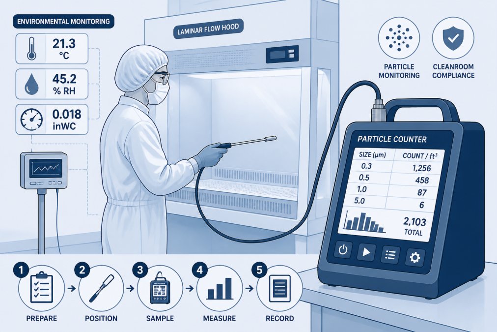
Lab technician in protective gown carefully positioning a particle counter sampling probe near a laminar flow hood in a pharmaceutical cleanroom, with the counter’s display screen visible and environmental monitoring equipment in the background
The sampling flow rate is critical. Most particle counters operate at a fixed flow rate (typically 0.1 CFM or 2.83 liters per minute). Verify this rate before starting, many instruments have a built-in flow meter or can be checked with an external flow calibrator.
Set your instrument’s detection threshold to match your regulatory requirement. For USP 797, you must count particles at 0.5 micrometers and 5.0 micrometers. Configure the counter to report counts in these size channels. Some instruments allow you to define custom size thresholds; use the instrument’s calibration data to ensure accuracy.
Establish your sampling duration. A minimum of one minute per location is standard for cleanroom certification, but longer sampling (three to five minutes) provides more stable statistics, especially in lower-contamination environments where particle counts are sparse. Record the actual sampling duration, it affects your final concentration calculation.
Contact Us →
Enable data logging on your instrument if available. Real-time logging allows you to review particle arrival patterns and detect anomalies. If counts spike suddenly during sampling, it may indicate a transient contamination event (door opening, personnel movement) rather than steady-state contamination. Document these events in your report.
Isokinetic sampling means the air velocity at the sampling probe entrance matches the bulk air velocity in the space. For laminar flow environments, this velocity is typically 80-120 feet per minute. For turbulent or mixed environments, determine the local velocity using a hot-wire anemometer or smoke visualization.
Adjust your probe orientation to align with the local air direction. In a laminar flow hood, this means pointing the probe in the direction of airflow. In a general cleanroom with mixed air patterns, position the probe to sample air moving toward your measurement location, not air that has already been sampled.
Begin sampling and allow the counter to accumulate data for the full duration you’ve specified. Most modern instruments display real-time particle counts, allowing you to monitor for anomalies. If you observe a sudden spike in counts, pause briefly to determine the cause, it may be a personnel movement, door opening, or equipment operation that temporarily increased contamination.
Record the final count and any observations. Note the time, location, environmental conditions (temperature, humidity, differential pressure), and any unusual events during sampling. This metadata is essential for interpreting results and troubleshooting if counts are unexpected.
Once sampling is complete, your instrument displays counts across multiple size channels. The key metric is the geometric standard deviation (GSD) of the particle size distribution. A GSD near 1.0 indicates a monodisperse aerosol (uniform size), while a GSD greater than 2.0 indicates a wide distribution of sizes.
For filter validation and contamination source identification, the shape of the size distribution reveals the source. Particles generated by personnel (skin cells, fibers) tend to cluster in the 1-10 micrometer range. Particles from air leaks or outdoor contamination often include a broader range, including sub-micrometer sizes. By analyzing the distribution shape, you can infer the dominant contamination mechanism.
Calculate the total particle concentration in your measurement volume. Most instruments do this automatically, but verify the calculation: sum all counts across size channels and divide by the sampling duration and flow rate. The result is particles per cubic meter (or particles per cubic foot, depending on your instrument).
Compare your measured concentration to your regulatory limit. For ISO Class 5, the limit is 3,520 particles/m³ at 0.5 micrometers. If your measurement exceeds this, investigate the source. For operational testing, this might mean reviewing personnel technique, checking HEPA filter integrity, or examining equipment off-gassing.
Particle counts that seem implausibly high or low often reflect measurement errors rather than actual contamination. The most frequent culprits are sampling flow rate drift, probe contamination, and environmental instability.
Flow rate drift is insidious because it’s invisible. A particle counter’s flow rate can decrease gradually over months of use as dust accumulates in the inlet filter or internal passages. A 10% reduction in flow rate produces a 10% underestimation of particle concentration. Solution: verify your flow rate weekly using an external calibrator. Replace inlet filters per manufacturer recommendations.
Probe contamination generates false positives. If your sampling probe has been used in a dusty environment and then moved to a cleanroom, residual particles in the probe entrance will be counted. Before sampling in a critical area, flush the probe with clean air from your facility for at least one minute. Better yet, use a dedicated probe for each environment classification.
Environmental instability causes counts to fluctuate wildly. If your cleanroom’s HVAC system cycles on and off during your sampling, air patterns shift and particle counts reflect this turbulence rather than true contamination. Solution: conduct all particle metrology testing during stable HVAC operation. Avoid sampling during facility startup or shutdown.
Optical path contamination inside the counter produces false positives. If the laser optics or photodetector are fouled, background noise increases and small particles trigger false counts. This is why regular cleaning (per manufacturer instructions) is essential. If counts suddenly increase without any facility changes, suspect optical contamination before assuming a real problem.
Isokinetic sampling errors bias your size distribution. If your probe is oriented perpendicular to airflow, larger particles preferentially enter the probe (aspiration bias), while smaller particles are deflected away. Result: your measured size distribution skews larger than reality. Always verify air direction before sampling and orient your probe accordingly.
Watch Out A subtle but critical error: sampling from the same location repeatedly without moving your probe. Particles settle and accumulate near the probe entrance, biasing subsequent measurements high. For periodic monitoring, rotate your sampling locations or allow the area to stabilize between measurements. For certification, use the pre-determined five-location protocol and don’t deviate.
Selecting the right instrument depends on your specific application, regulatory requirement, and budget. The core decision is between optical particle counters (OPC) and laser particle counters (LPC), and between single-channel and multi-channel detection.
Optical particle counters use traditional light-scattering technology and are suitable for most cleanroom applications. They’re reliable, well-established, and cost-effective. For USP 797 and ISO 14644 certification, an optical counter is typically sufficient.
Laser particle counters offer higher sensitivity and can detect sub-micrometer particles down to 0.1 micrometers. These are essential for semiconductor metrology and applications requiring sub-10nm detection capability. Applied Physics’s Automatic Laser Nanoparticle Size Analyzer delivers the precision required for advanced semiconductor nodes and research applications where particle size distribution analysis demands sub-micrometer resolution.
Automatic Laser Nanoparticle Size Analyzer
Single-channel counters report total particle count above a threshold size (e.g., “particles larger than 0.5 micrometers”). They’re simple and inexpensive but provide no information about particle size distribution.
Multi-channel counters bin counts into discrete size ranges (0.5, 1.0, 5.0, 10.0 micrometers, etc.), allowing you to analyze the size distribution and identify contamination sources. For regulatory compliance and troubleshooting, multi-channel capability is essential.
Aerosol generation is equally important. For filter validation and contamination source studies, you need an aerosol generator that produces uniform, traceable particle sizes. Applied Physics offers the Aerosol Photometer BAP-350 for HEPA validation in cleanrooms, electronics facilities, and medical environments. Cold-type generators like the BAG-4B and BAG-6D produce neutral aerosol without thermal bias, critical for accurate metrology.
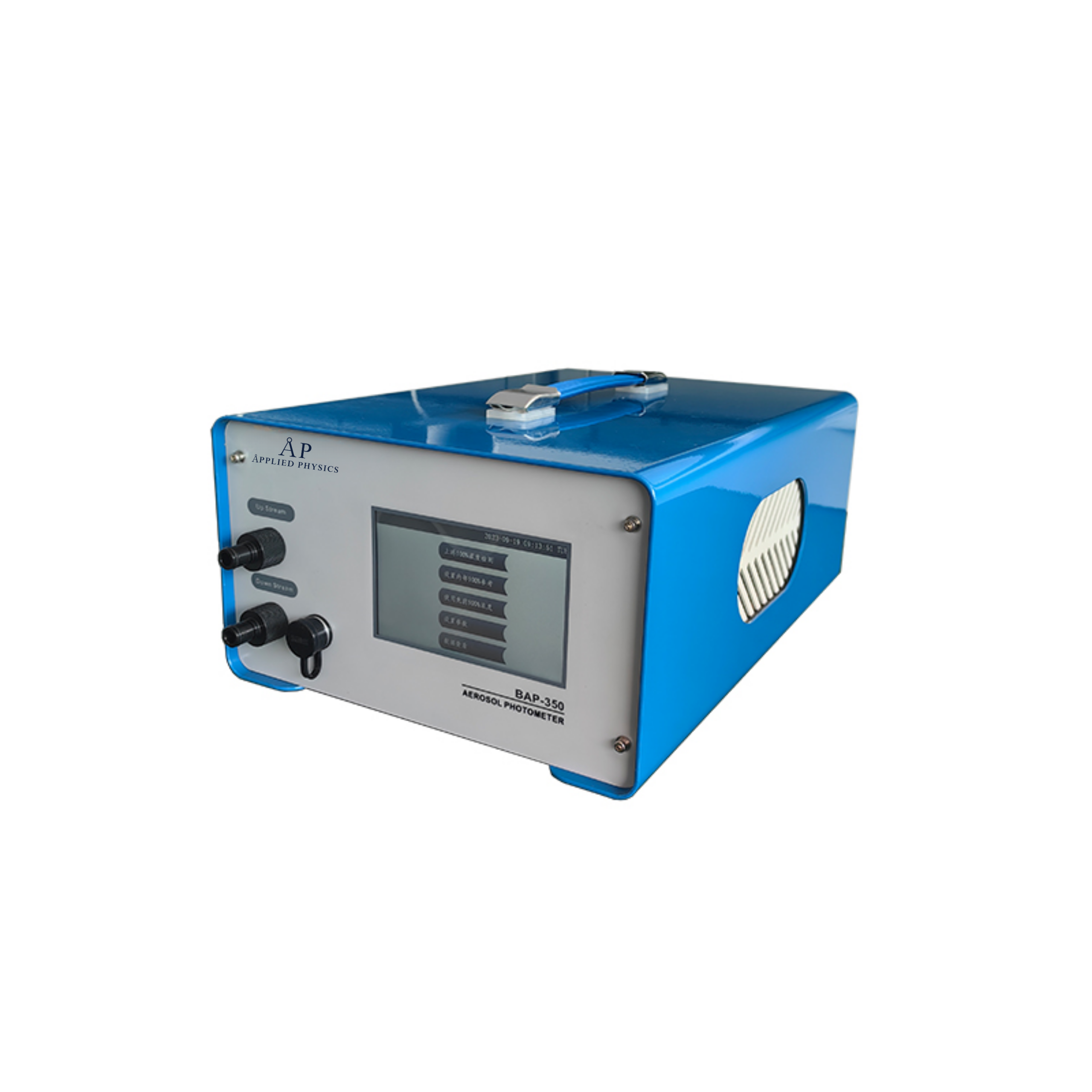
Aerosol Photometer BAP-350
When evaluating equipment, consider:
The lowest-cost instrument isn’t always the best choice. A cheap counter with poor optical design will generate inconsistent results, forcing you to repeat measurements and delaying corrective action. Invest in equipment from manufacturers with established metrology credentials, your compliance depends on it.
Particle metrology testing is the foundation of contamination control in regulated environments. From pharmaceutical compounding pharmacies validating USP 797 compliance to semiconductor fabs qualifying sub-10nm processes, accurate measurement of particle concentration and size distribution directly impacts product quality and regulatory standing.
The procedure itself is straightforward: prepare your environment, set your instrument parameters, conduct isokinetic sampling, and analyze the results. But execution requires attention to detail, flow rate verification, probe orientation, environmental stability, and proper calibration. A single measurement error can invalidate an entire certification study.
Applied Physics has supported contamination control programs for over three decades, providing the aerosol generators, particle counters, and calibration standards that enable precise particle metrology testing. Whether you’re establishing a new cleanroom certification, troubleshooting unexpected contamination, or validating filter integrity, the right equipment and methodology ensure your measurements are traceable, repeatable, and compliant. Contact Applied Physics to discuss your particle metrology testing requirements and discover how our precision instruments support your contamination control program.
Particle metrology testing measures airborne and liquid contamination in cleanrooms to verify compliance with GMP standards, ISO 14644 requirements, and USP 797 regulations. Testing validates that contamination control systems function correctly, identifies potential sources of micro-contamination, and ensures product safety in pharmaceutical, semiconductor, and biotech environments. Regular testing detects filter failures, validates HEPA filter integrity, and confirms that environmental monitoring meets regulatory thresholds.
Particle counters require calibration annually or per manufacturer specifications, and whenever equipment shows signs of drift or false negatives. Calibration uses reference standards such as latex spheres or aerosol generators to verify sensor sensitivity and detection accuracy. Documentation of all calibration events is mandatory for GMP compliance and regulatory audits. If your facility operates under USP 797 or ISO 14644 requirements, maintain calibration certificates and traceability records for all measurement instruments.
In situ measurement tests particles directly in your cleanroom or production environment, capturing real contamination data during normal operations. Laboratory measurement uses controlled aerosol generators and reference standards to validate equipment performance and calibration accuracy. Both approaches are required: in situ testing confirms your cleanroom meets operational standards, while laboratory measurement ensures your particle counter itself maintains precision and traceability. Combined, they provide comprehensive validation of your contamination control strategy.
First, verify that your sampling flow rate matches equipment specifications and that the isokinetic sampling technique is correct. Check for background noise or sensor sensitivity drift by running a calibration with reference standards. Inspect the optical particle counting sensor for contamination or damage. Confirm that your data acquisition settings align with your target particle size distribution range. If results remain inconsistent, contact the equipment manufacturer and document all troubleshooting steps for your regulatory file. Do not rely on data until the source of error is identified and resolved.
APPLIED PHYSICS TECHNICAL RESOURCE
Wafer inspection, SSIS calibration, particle deposition references, process control and semiconductor measurement workflows. Product and standards references should be interpreted for the actual instrument, facility, protocol and configuration.

Enter your details below to save your shopping cart for later. And, who knows, maybe we will even send you a sweet discount code :)
Allow notifications to get real-time updates about your shopping cart and who knows, you may even receive a sweet discount code 😊