
Table of Contents
- How Unidirectional Airflow Works to Prevent Contamination
- Principles of Unidirectional Airflow in Cleanroom Design
- HEPA Filtration and Air Quality in Unidirectional Systems
- Contamination Control Mechanisms in Laminar Flow Environments
- Cleanroom Airflow Visualization: Validating Unidirectional Flow Patterns
- Cleanroom Airflow Testing Methods for GMP Compliance
- Energy Efficiency Trade-Offs in Unidirectional Airflow Systems
- Common Failure Modes and Airflow Uniformity Issues
- Frequently Asked Questions
Last Updated: September 3, 2026
How Unidirectional Airflow Works to Prevent Contamination
Airborne particles follow predictable paths determined by air velocity, pressure differentials, and physical barriers. When airflow is unidirectional, every cubic foot of air moves in a single direction at controlled velocity, sweeping contaminants away from critical work zones before they settle on surfaces or products. If you control air direction and speed, you control where particles go. In a properly designed laminar flow system, contaminated air doesn’t recirculate into the clean zone, it’s captured, filtered through HEPA media, and either exhausted or recirculated after treatment, creating a protective envelope around sensitive operations.
The Physics of Laminar Airflow
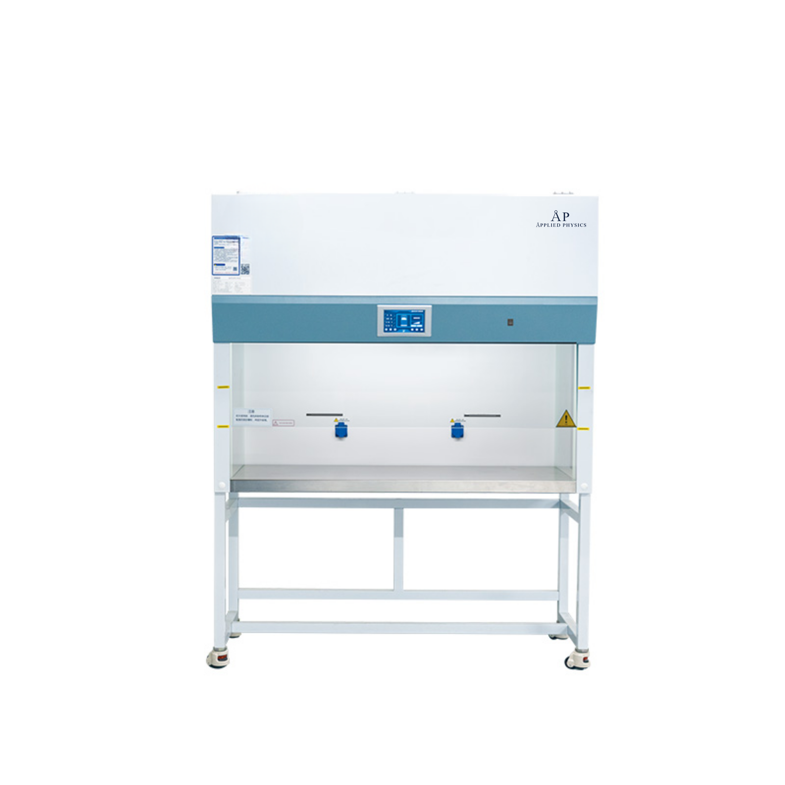
Laminar airflow occurs when air moves in parallel layers without mixing or turbulence. Each air molecule follows the same path as the one before it, creating uniform, predictable flow patterns. Most vertical laminar flow hoods operate at 80-120 feet per minute, while horizontal systems typically run at 90-110 feet per minute (iso.org). These speeds sweep particles away before they drift back into the work area, but not so fast that they create eddy currents or dead zones where contaminants can hide. When velocity drops below these thresholds, turbulence forms and contamination control fails.
Airflow Velocity and Particle Transport
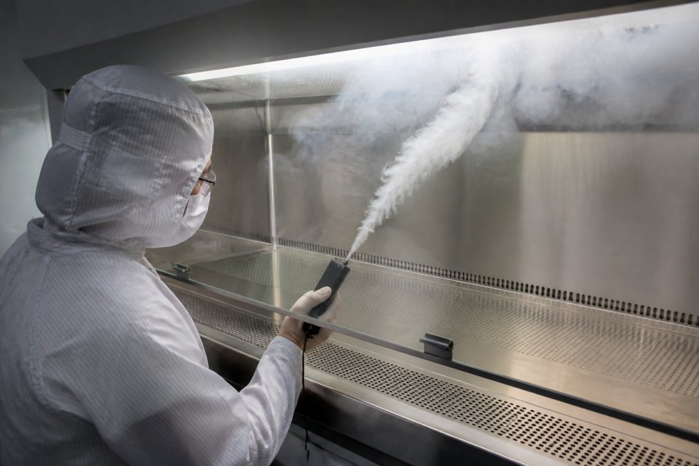
Particles suspended in air move with the air stream when air velocity exceeds the particle’s settling velocity. Larger particles settle faster; smaller particles remain suspended longer. With sufficient laminar velocity, even particles that would normally settle are carried away from critical surfaces. Applied Physics cleanroom foggers visualize this mechanism, tracer smoke shows particles moving at the same velocity as the air carrying them. Smooth, directional smoke movement indicates good airflow; stalling, reversing, or eddying indicates velocity problems. Contamination control focuses on particles in the 0.5-5 micron range, invisible to the naked eye but large enough to compromise product quality. A laminar flow system at proper velocity transports these particles away from the work zone regardless of size.
Principles of Unidirectional Airflow in Cleanroom Design
Unidirectional airflow operates on a single principle: air enters from one face, travels across the work zone, and exits from the opposite face or floor. The entire room volume participates in directional movement with no recirculation back into the clean zone. This differs fundamentally from conventional HVAC systems, which recirculate 70-80% of air. In unidirectional cleanrooms, air typically moves through once and is exhausted or recirculated only after complete HEPA filtration and reintroduction from the supply face.
Vertical vs. Horizontal Laminar Flow
Vertical laminar flow systems push air downward from ceiling-mounted HEPA filters toward exhaust grilles in the floor. Gravity assists downward movement, and particles naturally settle downward, so vertical flow aligns with particle behavior. This is the most common configuration in pharmaceutical compounding, biological safety work, and semiconductor fabrication. Horizontal laminar flow systems push air across the work zone from one wall to the opposite wall, common in semiconductor fabs where the work surface needs accessibility from multiple angles. Horizontal flow requires more powerful fans but provides better operator access. The choice depends on your process, vertical flow works well for single work surface protection; horizontal flow suits applications where product moves through the chamber and operators need side access.
Pressure Differential and Air Change Rates
Positive pressure (cleanroom pressure higher than surrounding areas) ensures that if any door opens or seal fails, clean air flows outward, not inward. This is your last line of defense against infiltration of contaminated air. Air change rates measure how many times the entire room volume is replaced per hour. A typical ISO Class 7 cleanroom requires 15-20 air changes per hour; an ISO Class 6 might require 40-60 air changes per hour. These rates ensure contamination is quickly swept away and filtered before settling on critical surfaces. Higher air change rates create higher pressure differentials but increase energy consumption and filter replacement frequency, a direct cost trade-off.
HEPA Filtration and Air Quality in Unidirectional Systems
HEPA filters remove 99.97% of particles 0.3 microns or larger from air passing through them (the FDA). This efficiency rating is absolute and tested, not estimated. However, HEPA efficiency only applies to air that actually passes through the filter. If airflow is turbulent or non-uniform, some air bypasses the filter media entirely. A HEPA filter in a poorly designed airflow system is like having a perfect lock on a broken door.
How HEPA Filters Remove Airborne Particles
HEPA filters work through three mechanisms: interception, impaction, and diffusion. Particles larger than 1 micron are captured by interception and impaction as they collide with filter fibers. Particles smaller than 0.1 microns are captured by diffusion as they bounce randomly and hit fibers. The 0.3-micron particles that HEPA filters are rated for fall in the middle, captured by a combination of all three mechanisms. The filter medium is a mat of randomly oriented fibers, typically fiberglass, creating a tortuous path that maximizes particle-fiber contact. Van der Waals forces hold particles in place once they make contact. If your airflow is unidirectional and uniform, all air supplying your work zone is guaranteed filtered. If airflow has dead zones or recirculation, some air bypasses this protection.
Filter Degradation and Maintenance Challenges
HEPA filters degrade gradually as particles accumulate. A new filter might create a 0.5-inch water column pressure drop; after six months it could be 1.5 inches; after a year, 2.5 inches. Your fan works harder, consuming more energy and generating more heat. The real problem emerges when filter degradation is uneven, if one section loads faster than others, airflow becomes non-uniform. You might maintain average velocity, but slow areas become contamination risk zones while fast areas waste energy. Detecting this requires regular airflow validation, not just pressure drop monitoring.
Contamination Control Mechanisms in Laminar Flow Environments
Contamination control in laminar flow works through three mechanisms: directional air movement sweeps particles away, HEPA filtration removes them from the air supply, and pressure management prevents external contamination from entering. The most effective contamination control happens before a particle reaches your critical surface, unidirectional airflow intercepts particles at their source and transports them away before they settle.
Cross-Contamination Prevention Strategies
Cross-contamination occurs when particles from one product or process contaminate another. Prevention starts with physical separation, different products should occupy different laminar flow cabinets or zones. But physical separation alone isn’t enough if overall room airflow is chaotic. If room air is unidirectional and uniform, particles generated in one area are swept toward exhaust, not toward adjacent work zones. Operational discipline is the second strategy: operators should move with the airflow, not against it. In vertical laminar flow hoods, work below the filter face so particles are swept downward. In horizontal systems, position yourself to the side of the airflow path. The third strategy is validation, you must prove cross-contamination won’t happen through particle counting at different locations and smoke testing to visualize actual airflow patterns.
Protecting Critical Surfaces from Airborne Contaminants
Critical surfaces, product contact surfaces, work tables, and equipment, must remain uncontaminated. Protection starts with positioning: critical surfaces should be directly in the path of clean air supply, not in areas where air has already traveled and picked up particles. The second layer is air velocity, if velocity is high enough, particles won’t settle on the critical surface but will be swept away. This is why velocity validation is non-negotiable. The third layer is contamination barriers like perforated work surfaces, ULPA filters in critical zones, or air curtains. These are supplementary measures, not replacements for proper unidirectional airflow.
Cleanroom Airflow Visualization: Validating Unidirectional Flow Patterns
You cannot manage what you cannot see. Airflow visualization transforms the abstract concept of “unidirectional airflow” into observable reality. Without visualization, you’re assuming your system works as designed; with visualization, you know it does. Smoke testing is the most direct method, when you introduce tracer smoke into a laminar flow system, you watch particles move with the air. Uniform, directional smoke movement indicates good airflow; stalling, swirling, or reverse flow indicates problems needing correction.
Smoke Testing and Flow Pattern Assessment
Mechanical smoke is preferred for laminar flow validation because it behaves like the particles you’re controlling, it moves with the air, not against it. Introduce smoke at various points within the cleanroom and observe its movement. Smoke should move smoothly in one direction without swirling or stalling. Stalling near a work surface indicates a dead zone; reverse direction indicates recirculation; different speeds in different areas indicate non-uniform flow. Applied Physics cleanroom foggers produce neutral-density particles that don’t rise or fall on their own, moving purely with the air for an accurate picture of actual airflow behavior. Once you’ve visualized airflow patterns, you can make informed decisions about equipment placement, operator positioning, and contamination control measures.
Real-Time Airflow Monitoring Tools
Continuous airflow monitoring provides ongoing validation beyond smoke testing. Anemometers measure air velocity at specific points; particle counters measure particle concentration at different locations. Together, they create a real-time picture of whether your system maintains validated conditions. The challenge is cost and complexity, high-quality equipment is expensive and requires planning and maintenance. Many facilities use continuous monitoring in critical zones and periodic validation elsewhere. The real value is early warning: if velocity drops or particle counts rise, you know there’s a problem before contamination occurs, allowing preventive maintenance rather than reactive troubleshooting.
Cleanroom Airflow Testing Methods for GMP Compliance
Good Manufacturing Practice compliance requires documented evidence that your cleanroom maintains specified conditions. For most pharmaceutical operations, this means proving airflow is unidirectional, velocity is within specification, and particle counts are below limits. Testing methods are standardized and recognized by the FDA.
ISO Cleanroom Classification Standards
ISO 14644 defines cleanroom classification based on particle count limits. An ISO Class 5 cleanroom must maintain no more than 3,520 particles 0.5 microns or larger per cubic meter (iso.org). An ISO Class 6 allows 35,200 particles per cubic meter. An ISO Class 7 allows 352,000 particles per cubic meter. These limits are absolute, your cleanroom either meets the classification or it doesn’t. Classification is determined through particle counting at specific locations. If all measurements are below the limit for your target classification, you pass; if any exceeds the limit, you fail. Classification can change as filters degrade, equipment fails, or procedures change, which is why periodic requalification is required, typically annually.
Particle Count Validation and Turbulence Reduction
Particle counting measures how well contamination control is working, but particle counts alone don’t tell the whole story. You also need to know particles aren’t being generated by turbulence within your cleanroom. Turbulence reduction is achieved through proper airflow design and maintenance: smooth air supply without obstacles, properly sized exhaust, and adequate air change rates. The relationship between airflow velocity and turbulence is non-linear, below 70 feet per minute, turbulence increases dramatically; above 120 feet per minute, you’re wasting energy without proportional benefits. The sweet spot is typically 80-110 feet per minute. Detecting turbulence requires both particle counting for quantitative compliance data and smoke testing for qualitative assessment of airflow patterns.
Energy Efficiency Trade-Offs in Unidirectional Airflow Systems
Unidirectional airflow systems consume significant energy. A typical vertical laminar flow hood operating 8 hours per day uses about 2-3 kilowatts continuously. A full-room cleanroom with 40-60 air changes per hour can consume 50-100 kilowatts or more. The energy cost is real, but the contamination cost of inadequate airflow is higher. A single contaminated batch can cost far more than a year of elevated energy consumption. The trade-off isn’t between energy efficiency and contamination control, it’s between accepting the energy cost or accepting the contamination risk. Variable air volume systems that adjust fan speed based on actual demand can reduce energy consumption by 20-30% compared to constant-velocity systems. Properly maintained filters that don’t become excessively loaded reduce fan energy requirements. Real optimization comes from matching airflow to actual need rather than oversizing for hypothetical future requirements.
Common Failure Modes and Airflow Uniformity Issues
Unidirectional airflow systems fail in predictable ways. The most common failure is velocity degradation, as filters load, fan bearings wear, or ductwork develops leaks, airflow velocity drops below the threshold needed for effective contamination control. The second common failure is non-uniform flow, where different areas receive different air velocities due to partial filter blockage, obstacles creating dead zones, or unevenly distributed exhaust grilles. The third failure mode is recirculation, where exhaust design allows air to recirculate back into the supply stream, recycling contaminated air.
Detecting Dead Zones and Flow Disruptions
Dead zones are areas where airflow stalls. They occur downstream of obstacles, in corners where air can’t easily reach, or where exhaust is distant. Particles in dead zones settle out rather than being swept away. Smoke testing reveals dead zones immediately, smoke will stall or move very slowly in these areas. Particle counting can also reveal dead zones if you measure at multiple locations; significantly higher particle counts in theoretically clean areas likely indicate a dead zone problem.
Addressing Airflow Uniformity Degradation
When airflow becomes non-uniform, the solution depends on the root cause. Uneven filter loading requires filter replacement. Obstacles creating turbulence require removal or repositioning. Unevenly distributed exhaust grilles require rebalancing. Non-uniform flow often develops gradually, you might not notice one area drifting from 100 to 70 feet per minute, but that degradation is significant and increases contamination risk. Periodic validation catches these problems while still minor.
Schedule smoke testing and velocity validation annually, or more frequently if you’ve made changes to equipment, layout, or HVAC configuration. Early detection of airflow degradation prevents contamination events and reduces corrective action costs.
Why unidirectional airflow prevents contamination comes down to physics and discipline. You control air direction and speed, filter that air to remove particles, and maintain pressure differentials to prevent external contamination from entering. The science is proven. The challenge is maintaining these conditions consistently over time, validating that they’re actually being maintained, and investing in the energy and maintenance costs that effective contamination control requires. For facilities managing pharmaceutical compounding, semiconductor fabrication, or biotech research, the stakes justify the investment. Applied Physics has supported organizations in these industries since 1992, providing cleanroom foggers for airflow visualization, calibration wafer standards for metrology validation, and technical expertise to ensure your contamination control strategy actually works. When contamination risk is high and regulatory requirements are strict, precision contamination control is the foundation of operational excellence.
Contact Applied Physics to discuss your specific airflow validation needs and how our contamination control solutions can support your GMP compliance requirements.
Frequently Asked Questions
Why is unidirectional airflow essential for ISO-classified cleanrooms?
Unidirectional airflow maintains cleanroom classification by ensuring consistent particle removal and preventing cross-contamination. ISO standards (ISO 14644-1) require specific air change rates and laminar flow velocity to achieve particle count limits. In a pharmaceutical cleanroom, unidirectional airflow directed downward or horizontally sweeps airborne contaminants away from critical surfaces and work zones, meeting USP 797 requirements for sterile compounding and GMP compliance in drug manufacturing.
How does cleanroom airflow visualization help validate unidirectional flow patterns?
Cleanroom airflow visualization uses smoke testing and particle tracing to confirm that laminar flow patterns are uniform and unobstructed. Foggers release visible tracer particles that follow airflow, revealing dead zones, turbulence, or flow reversals that could allow contaminants to reach critical surfaces. This testing method is essential for GMP audits and certification; it documents that your system maintains the required airflow uniformity and velocity to prevent contamination.
What happens when HEPA filters degrade in an unidirectional airflow system?
Degraded HEPA filters lose efficiency in removing airborne particles, reducing the quality of air entering the cleanroom and compromising unidirectional flow effectiveness. As particulate matter accumulates, pressure drop increases, which can distort airflow velocity and uniformity. Regular filter testing and replacement, typically when pressure differential reaches manufacturer limits, is critical to maintain laminar flow performance and prevent contamination incidents that could trigger regulatory action.
How do you detect real-world airflow failures before they cause contamination?
Real-world failures are detected through periodic cleanroom airflow testing methods: particle count monitoring, smoke visualization, and velocity measurements at multiple points. Common failure modes include filter bypass, obstruction of return air vents, and temperature stratification that disrupts laminar flow. Regular validation using foggers or particle counters catches these issues early, preventing product loss and compliance violations in pharmaceutical and semiconductor environments.
