Last Updated: July 22, 2026
Understanding how to validate cleanroom airflow patterns is essential for any facility handling pharmaceuticals, semiconductors, or sterile medical devices. According to ISO 14644 standards, improper airflow validation is one of the primary causes of contamination failures in regulated environments. Below, we’ll walk you through exactly how to validate cleanroom airflow patterns using proven methods that meet GMP, FDA, and EU regulatory requirements.
A single contamination event can shut down production for weeks, trigger regulatory investigations, and damage your facility’s reputation. Yet many teams approach airflow validation reactively, only testing after problems emerge. This guide shows you the proactive approach: systematic validation that prevents failures rather than discovering them too late.
Cleanroom airflow validation is the process of verifying that air movement within a controlled environment follows the intended pattern and maintains proper contamination control. This is a regulatory requirement. The FDA, EMA, and USP all mandate documented evidence that airflow patterns support the cleanroom’s intended classification and function.
Air is your primary contamination barrier. When airflow breaks down, dead zones form, recirculation occurs, or turbulence develops, particles bypass your HEPA and ULPA filters and settle on critical surfaces. A smoke study reveals exactly where these failures happen.
Validation isn’t a one-time event. Cleanroom design changes, equipment moves, filter degradation, and HVAC modifications all alter airflow patterns. Continuous monitoring and periodic re-validation keep your facility compliant and your product safe.
Three primary airflow patterns define cleanroom operation. Understanding the differences is critical because each pattern has different validation requirements and failure modes.
Laminar flow (also called unidirectional flow) moves air in parallel lines at uniform velocity from one wall to another. In a vertical laminar flow cleanroom, HEPA-filtered air enters from the ceiling and exits through perforated floor returns. When functioning correctly, laminar flow sweeps contaminants directly out of the space before they can settle on product.
Turbulent airflow (also called non-unidirectional flow) mixes air throughout the cleanroom rather than moving it in one direction. Air enters through multiple points and exits through multiple returns, creating circulation patterns that depend on the specific HVAC configuration. Turbulent flow cleanrooms typically achieve lower classifications (Class 7 or 8 per ISO 14644) and rely on air changes per hour (ACH) rather than directional flow for contamination control.
Unidirectional flow is the most common pattern in pharmaceutical and semiconductor cleanrooms. It provides superior contamination control by continuously sweeping particles toward exhaust. However, unidirectional flow is also the most sensitive to disruption. A misplaced piece of equipment, a blocked return vent, or degraded filter performance can destroy the pattern entirely.
Dead zones are areas where air velocity drops to near zero, typically corners or spaces blocked from direct airflow. Recirculation occurs when exhaust air is drawn back into the supply, reducing filtration effectiveness. Both patterns indicate contamination pathways where particles can accumulate. A smoke study reveals these problems visually; velocity mapping quantifies them numerically.
An airflow visualization study uses visible tracers, typically smoke or aerosol particles, to show how air actually moves through your cleanroom. This is fundamentally different from theoretical airflow modeling. You’re observing reality, not predictions.
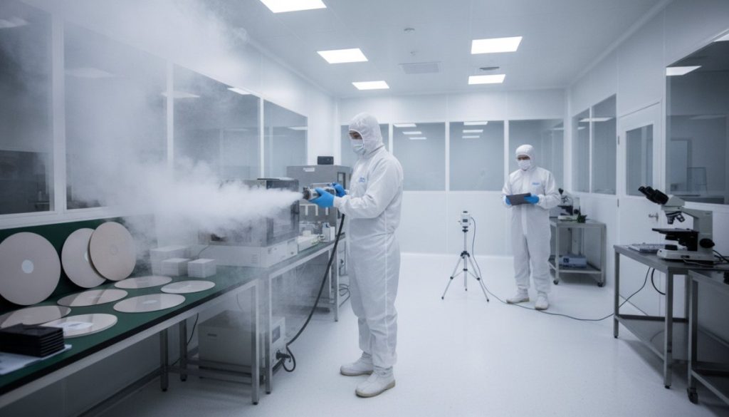
Smoke testing and particle tracing form the foundation of airflow visualization. A smoke generator releases visible particles into the cleanroom supply air or directly into the space. As these particles follow the airflow, you observe their path: Do they move smoothly toward exhaust? Do they swirl and stall? Do they move backward? The smoke’s behavior tells you everything about your airflow pattern.
Applied Physics provides both ultrapure LN2 foggers and ultrasonic cold-type aerosol generators for cleanroom validation work. The choice depends on your cleanroom classification and sensitivity requirements. Higher classifications require neutral fog that doesn’t interfere with particle counts or contaminate the space.
Velocity mapping and anemometer measurements quantify what smoke studies show visually. An anemometer measures air velocity at specific points throughout the cleanroom. You create a grid of measurement locations, record velocity at each point, and plot the results. This produces a velocity map showing where airflow meets specifications (typically 0.3-0.5 meters per second for laminar flow) and where it falls short.
The ISO 14644 standard for cleanroom classification requires velocity mapping at multiple heights and locations. This isn’t optional documentation; regulators expect to see these measurements in your validation file.
Gather your equipment: a smoke generator, an anemometer, differential pressure gauges, thermometers, and humidity monitors. Clear the cleanroom of unnecessary personnel and equipment. Close doors and seal any temporary openings. Stabilize environmental conditions by allowing the HVAC system to run for at least 15 minutes at normal operating parameters. Record baseline temperature, humidity, and pressure differentials.
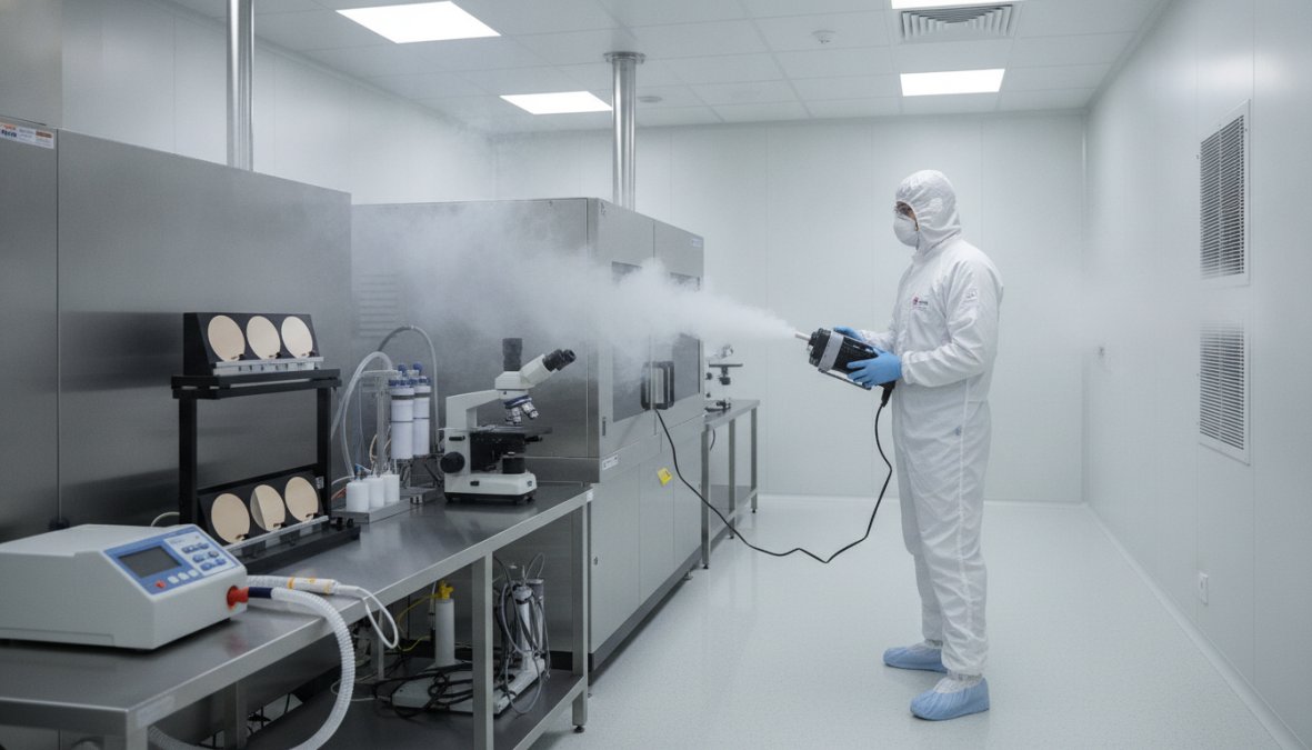
If conducting an at-rest study, ensure the space is genuinely at rest. If conducting an in-operation study, position equipment and personnel exactly as they’ll be during actual production. The airflow pattern with equipment present can differ significantly from the empty-space pattern.
Position your smoke generator at the cleanroom supply air intake or at a central location within the space. Start the generator and release smoke gradually. Controlled, visible smoke is what you need, not flooding the space.
Observe the smoke movement carefully. Does smoke move smoothly from supply to exhaust? Does it swirl or stall in any area? Does it move backward toward supply? Take video or still photographs documenting the airflow pattern. These become part of your validation record.
Pay particular attention to corners, spaces behind equipment, and areas near exhaust vents. These are high-risk zones for dead zones and recirculation.
Document everything you observe. For each area of the cleanroom, record:
Create a visual map of your cleanroom showing these observations. Use arrows to indicate airflow direction and note problem areas. If you identify airflow problems, photograph or video-record them. This documentation helps you communicate the issue to your HVAC contractor and verify corrections after remediation.
Using an anemometer, measure air velocity at predetermined grid points throughout the cleanroom. For laminar flow cleanrooms, measure at multiple heights (typically 0.3 meters above work surface, 0.6 meters, and 0.9 meters). Record each measurement and calculate average velocity.
For unidirectional flow, specifications typically require 0.3-0.5 m/s average velocity with no point below 0.2 m/s. If your measurements fall outside these ranges, airflow requires adjustment.
Measure pressure differentials using differential pressure gauges. Your cleanroom should maintain positive pressure relative to adjacent areas (typically 12-25 Pa for pharmaceutical cleanrooms). If pressure is low or negative, air is leaking out rather than containing contamination.
| Measurement Type | Typical Specification | Why It Matters |
|---|---|---|
| Average Velocity (Laminar) | 0.3-0.5 m/s | Ensures adequate sweep velocity for contamination removal |
| Minimum Velocity | ≥0.2 m/s at any point | Prevents dead zones where particles can accumulate |
| Pressure Differential | +12 to +25 Pa | Maintains containment and prevents contamination ingress |
| Air Changes Per Hour | 15-20 ACH minimum | Ensures adequate air circulation for contamination dilution |
Comprehensive cleanroom validation follows a four-stage protocol established by GMP guidelines. Each stage builds on the previous one, creating a documented evidence trail that satisfies regulatory requirements.
Design Qualification (DQ) occurs before construction or major modifications. You document the intended cleanroom design: classification, airflow pattern, HVAC specifications, equipment placement, and contamination control strategy. DQ answers: "Is this design adequate to achieve the required contamination control?"
Installation Qualification (IQ) verifies that the installed system matches the design specifications. You confirm HVAC equipment is correctly installed, filters are proper type and rating, supply and exhaust points are positioned as designed, and pressure differential systems function correctly.
Operational Qualification (OQ) tests the system under controlled conditions. You run the HVAC system and measure airflow patterns, pressure differentials, and particle counts under at-rest conditions (no personnel or equipment operating).
Performance Qualification (PQ) validates the system under actual operating conditions with personnel and equipment present. You measure airflow, pressure, and particle counts during simulated or actual production activities.
At-rest validation (typically part of OQ) measures your system’s baseline performance with the space empty. In-operation validation (PQ) measures performance during actual work. Both are required because airflow patterns change when people move, equipment operates, and doors open and close.
Your cleanroom’s physical layout determines whether optimal airflow patterns are even possible. Poor design can’t be fixed with better HVAC maintenance.
HVAC system configuration and HEPA/ULPA filter placement are foundational decisions. For vertical laminar flow, HEPA filters must be installed in the ceiling with supply air moving downward. For horizontal laminar flow, filters must be in one wall with air moving across to the opposite wall. The location of exhaust returns matters equally. In vertical laminar flow, returns should be positioned at floor level around the perimeter, allowing air to exit after sweeping across work surfaces.
Equipment placement within the cleanroom affects airflow significantly. Large equipment blocks airflow and creates dead zones downstream. Position equipment to minimize obstruction of the primary airflow path. If equipment must be placed in a high-risk location, consider supplemental local filtration or modified HVAC design to maintain adequate airflow around it.
Doorways and airlocks interrupt airflow patterns. Design cleanroom access to minimize these disruptions. Airlocks with interlocking doors, pass-through chambers, and separate supply/exhaust for entry areas all help maintain airflow integrity during personnel movement.
Cleanroom validation operates within a framework of international and regulatory standards. Understanding these requirements ensures your validation effort actually satisfies regulators.
The ISO 14644 standard for cleanroom classification and control defines cleanroom classifications (Class 1 through Class 9) based on particle count limits. It also specifies validation requirements including airflow pattern testing, velocity mapping, and pressure differential measurement.
GMP and FDA requirements for pharmaceutical cleanrooms are defined in FDA guidance documents and USP standards. The FDA’s guidance on sterile drug product manufacturing requires documented evidence that cleanroom design and operation maintain aseptic conditions. This evidence must include airflow validation studies conducted during qualification and repeated periodically during operation.
EU GMP Annex 1 and aseptic processing standards impose similar requirements for European facilities. EU GMP Annex 1 specifies that cleanrooms for aseptic processing must maintain unidirectional airflow at specified velocities, and this must be verified through regular testing. The standard requires re-qualification after any modification that could affect airflow.
Regulatory inspections focus on three things: (1) Does your cleanroom design match your validation protocol? (2) Do your validation results demonstrate adequate contamination control? (3) Is your validation documentation complete and properly maintained?
Years of validation work reveal recurring patterns of failure. Knowing what goes wrong helps you identify and correct problems in your facility.
Identifying and correcting dead zones and turbulence requires systematic observation. Dead zones typically occur in corners, behind large equipment, or in areas blocked from direct airflow. If your smoke study reveals stalled smoke in any area, you’ve found a dead zone.
Correcting dead zones depends on the root cause. If the problem is blocked airflow, reposition or remove the obstruction. If the problem is inadequate supply air velocity, adjust HVAC settings to increase flow. If the problem is poor exhaust positioning, relocate exhaust vents to ensure air can exit the dead zone area.
Turbulence, indicated by erratic, swirling smoke movement, suggests air velocity is too high or airflow is impacting obstructions. Reduce supply air velocity or reposition supply outlets to eliminate the impact point.
Equipment interference and contamination pathways emerge when equipment placement disrupts designed airflow. A large piece of equipment placed directly downstream of the supply air creates a shadow zone where airflow stalls. Equipment positioned in front of exhaust returns blocks air exit and causes recirculation.
The fix requires either repositioning equipment or modifying HVAC design. If repositioning isn’t feasible, consider local supplemental filtration or modified supply/exhaust design to maintain airflow around the obstruction.
Conducting professional airflow validation requires specific instruments. Understanding what each tool does helps you select the right equipment for your facility’s needs.
Smoke generators, aerosol photometers, and differential pressure gauges form the core validation toolkit. A smoke generator releases visible particles into the air. Applied Physics offers both ultrapure LN2 foggers and cold-type aerosol generators for pharmaceutical cleanroom testing that produce neutral fog suitable for high-classification cleanrooms.
An aerosol photometer measures particle concentration in real time. The Aerosol Photometer BAP-350 is commonly used for HEPA filter leak detection and cleanroom particle count verification. Differential pressure gauges measure the pressure difference between your cleanroom and adjacent areas. An anemometer measures air velocity at specific points and allows you to create velocity maps.
In-house basic checks vs. professional validation services represent different approaches with different trade-offs. In-house checks using basic equipment can identify gross airflow problems and are suitable for routine monitoring between professional validations. However, in-house checks lack the documentation rigor and instrument calibration that regulatory inspections expect.
Professional validation services bring calibrated instruments, trained technicians, and comprehensive documentation. For initial qualification and periodic re-qualification, professional services are typically necessary. For routine monitoring, in-house checks can supplement professional services.
Airflow validation requires resources, and understanding these costs helps you budget appropriately and minimize disruption.
A professional airflow validation study typically requires 1-3 days depending on cleanroom size and complexity. During this time, your cleanroom is offline and no production can occur. Scheduling validation during planned maintenance windows or lower-production periods minimizes impact.
Equipment costs for in-house validation range from modest (a basic smoke generator and anemometer) to substantial (calibrated instruments and data logging systems). Professional validation services cost between $2,000 and $10,000 depending on cleanroom size, complexity, and scope of documentation.
The true cost of skipping validation isn’t the validation expense; it’s the cost of undetected contamination failures. A single batch loss due to contamination can exceed $100,000 for pharmaceutical manufacturing. Regulatory findings trigger investigations, corrective actions, and potentially product recalls. The cost of validation is trivial compared to the cost of failure.
| Validation Approach | Cost Range | Time Required | Best For |
|---|---|---|---|
| In-house basic checks | $500-2,000 equipment | 4-8 hours | Routine monitoring between professional validations |
| Professional initial qualification | $3,000-8,000 | 2-3 days | First-time validation or major cleanroom modifications |
| Professional re-qualification | $2,000-5,000 | 1-2 days | Periodic compliance verification (typically annual) |
| Comprehensive DQ/IQ/OQ/PQ | $8,000-15,000 | 4-5 days | New cleanroom construction or major system changes |
Validating cleanroom airflow patterns isn’t optional; it’s the foundation of contamination control. When your validation study reveals problems, you have the evidence to justify corrections before contamination reaches your product. Applied Physics helps pharmaceutical, semiconductor, and medical device manufacturers implement rigorous airflow validation protocols using precision foggers, aerosol photometers, and calibrated measurement equipment. Contact Applied Physics to discuss how our airflow visualization solutions can strengthen your cleanroom’s contamination control and ensure regulatory compliance.
An airflow visualization study reveals how air moves through your cleanroom, identifying laminar flow patterns, turbulent zones, and dead zones where contamination can accumulate. Using smoke generators or tracer particles, you can observe actual airflow behavior under at-rest and in-operation conditions. This visual confirmation ensures your HVAC system, HEPA filters, and room layout deliver the contamination control your process requires, supporting GMP compliance and regulatory validation.
ISO 14644 and GMP guidelines require initial validation during installation qualification (IQ) and operational qualification (OQ) phases. Many facilities conduct annual re-validation or whenever significant changes occur, such as equipment relocation, HVAC maintenance, or filter replacement. Some pharmaceutical operations performing aseptic processing under EU GMP Annex 1 may validate more frequently. Your risk assessment and regulatory obligations should determine the specific schedule for your cleanroom classification level.
For in-house basic checks, you'll need a smoke generator (such as a cold aerosol generator), an anemometer to measure velocity, and differential pressure gauges to monitor pressure differentials across filters. An aerosol photometer helps verify particle count and HEPA filter integrity. Applied Physics offers the Aerosol Generator BAG-4B and BAG-6D for glove boxes and cleanrooms, plus the Air Volume Meter BK-AVM-1 for velocity measurements. Professional validation studies also employ CFD analysis and comprehensive documentation for regulatory audits.
Laminar (unidirectional) airflow flows in one direction at uniform velocity, sweeping contaminants out consistently, ideal for aseptic processing. Turbulent airflow mixes in multiple directions and can create dead zones where particles settle. Most pharmaceutical cleanrooms require laminar flow to meet ISO 14644 classification and FDA/GMP standards. Turbulent patterns increase contamination risk and are only acceptable in lower-classification areas. Your airflow visualization study should confirm that your design delivers the required pattern type.
This article was written using GrandRanker

Enter your details below to save your shopping cart for later. And, who knows, maybe we will even send you a sweet discount code :)
Allow notifications to get real-time updates about your shopping cart and who knows, you may even receive a sweet discount code 😊