

As semiconductor manufacturing pushes beyond the 5 nm logic node, Extreme Ultraviolet (EUV) lithography has become the undisputed engine of modern chipmaking.
However, operating at a wavelength of 13.5 nm introduces unprecedented physical and chemical sensitivities.
Among the most complex hurdles in maximizing EUV uptime and yield is molecular contamination, specifically within the EUV reticle pods that store and transport the critical photomasks.
This guide breaks down the mechanics of molecular contamination, its impact on high-volume manufacturing (HVM), and the industry’s most effective strategies for mitigating these invisible threats.
Unlike particulate contamination (physical dust or debris), Airborne Molecular Contamination (AMC) consists of chemical vapors and volatile organic compounds (VOCs) that adsorb onto sensitive surfaces.
In traditional optical lithography, molecular contamination often leads to haze crystalline defects formed by reactions of ammonia, sulfates, and moisture.
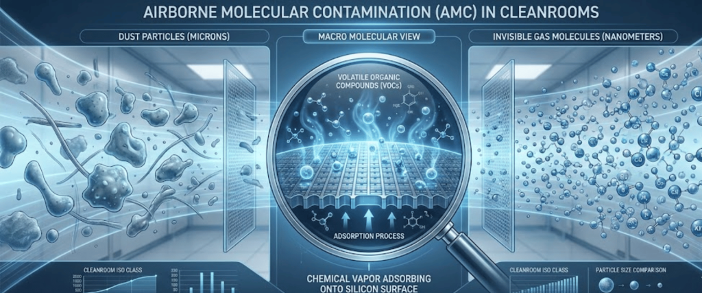
In EUV lithography, the physics change dramatically. EUV photons possess extremely high energy ($92\text{ eV}$), which is more than enough to trigger the photo-dissociation of almost any organic molecule present in the vacuum environment.
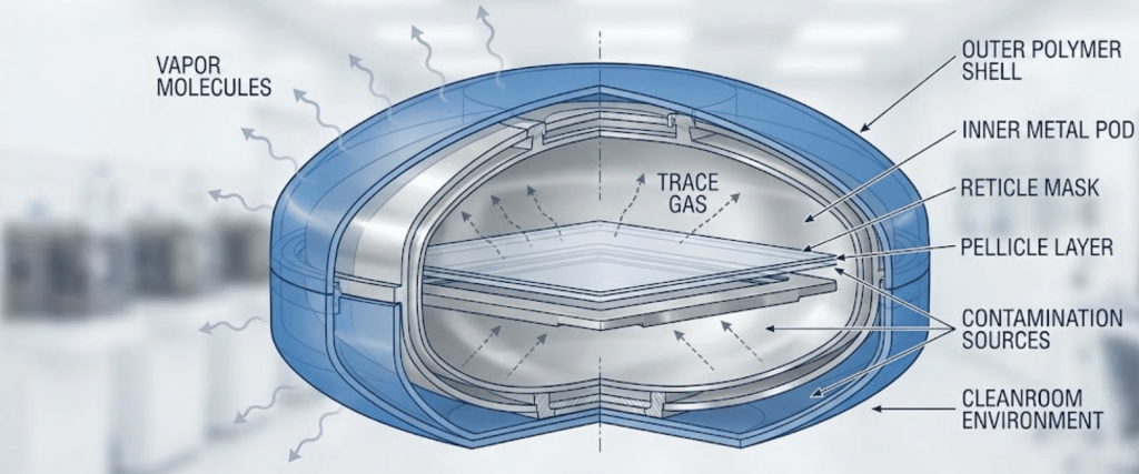
When an EUV reticle is housed within a pod, it is vulnerable to trace gases and outgassing from several sources.
When a reticle carrying a thin layer of adsorbed hydrocarbons is loaded into the scanner and hit with EUV light, those molecules undergo photoelectron cracking.
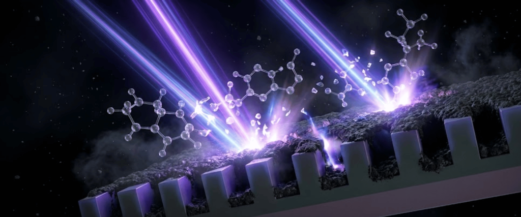
The result is a progressive accumulation of amorphous carbon directly on the illuminated areas of the reticle both on the capping layer of the Mo/Si multilayer mirror and the absorber sidewalls.
This carbonization has direct, costly consequences on lithographic performance.
Because a single EUV scanner represents a nine-figure investment, contamination control is no longer just a cleanroom discipline; it is an ecosystem-wide necessity.
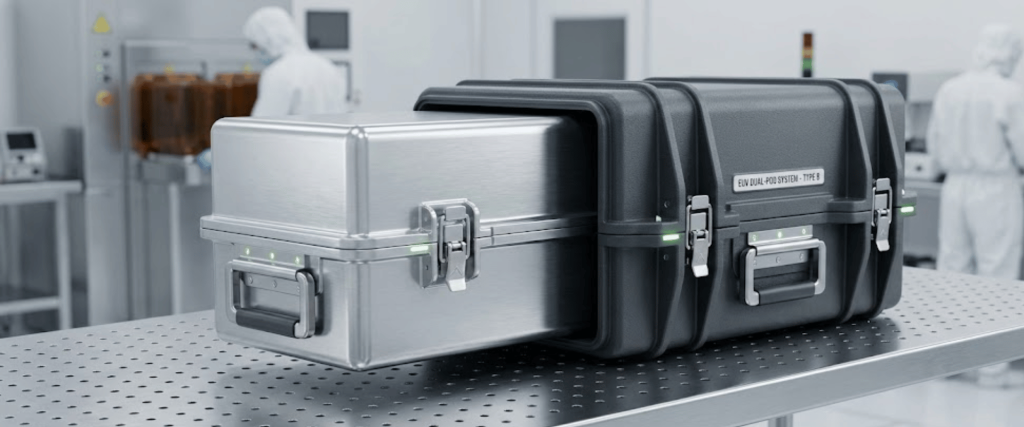
To combat both particulate and molecular threats, the industry relies on a specialized dual-pod standard.
One of the most effective ways to starve the carbonization process is to eliminate the precursor molecules entirely.
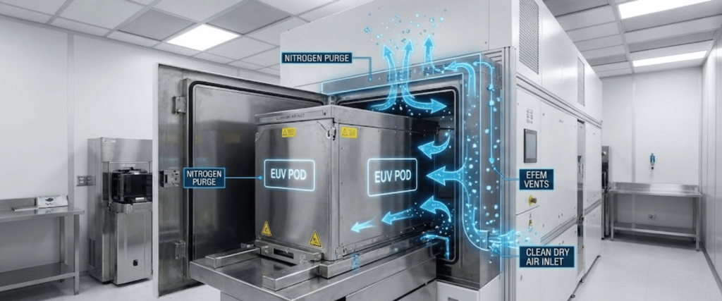
Cleanrooms use advanced chemical filters (AMC filters) above critical minienvironments.

In conjunction, fab operators utilize in-line real-time monitoring systems capable of detecting volatile organics, acids, and amines down to the $100\text{ ppt}$ level within the pod micro-environments.
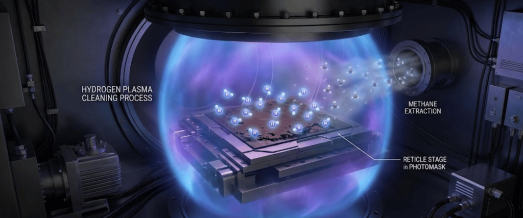
Because some carbon deposition is practically unavoidable over a reticle’s lifespan, modern EUV scanners utilize in-situ cleaning mechanisms.
The shift to Extreme Ultraviolet lithography has transformed molecular contamination from a minor nuisance into a major threat to optical transmission and throughput.
Controlling volatile organic compounds through strict material selection and ultra-clean micro-environments is essential to prevent carbon-induced reflectivity loss on delicate reticles.
Implementing rigorous AMC filtration and queue time optimization minimizes the risks associated with polymer and pellicle outgassing.
Moving forward, mastering these mitigation strategies will be the defining factor in achieving profitable, defect-free production at advanced logic nodes.
It is primarily caused by outgassing from polymer pod components, pellicles, and trace cleaning chemical residues.
Carbon absorbs EUV light, leading to a significant loss in mirror reflectivity, altered critical dimensions, and reduced wafer throughput.
It is a specialized two-part storage system featuring a non-outgassing inner pod and a durable, static-dissipative outer shell to block contaminants.
The high-energy ($92\text{ eV}$) EUV photons easily break down surrounding organic molecules, causing rapid carbon buildup on the optics.