In the ultra-sensitive environments of semiconductor fabrication and pharmaceutical depyrogenation, air purity is non-negotiable. High-Efficiency Particulate Air (HEPA) filters are the primary defense against contamination.
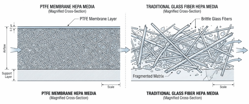
However, modern manufacturing increasingly relies on Polytetrafluoroethylene (PTFE) media filters rather than traditional glass fiber, especially in high-temperature zones.
While PTFE offers superior chemical resistance and durability, verifying its integrity presents unique challenges, particularly under the thermal stress of high-temperature cleanrooms.
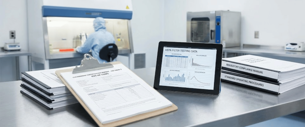
This article outlines the technical methodologies for accurately verifying PTFE HEPA filter integrity, ensuring compliance with ISO 14644-3 and IEST-RP-CC001.
Traditional micro-glass media has long been the standard, but it poses significant risks in specific high-tech applications.
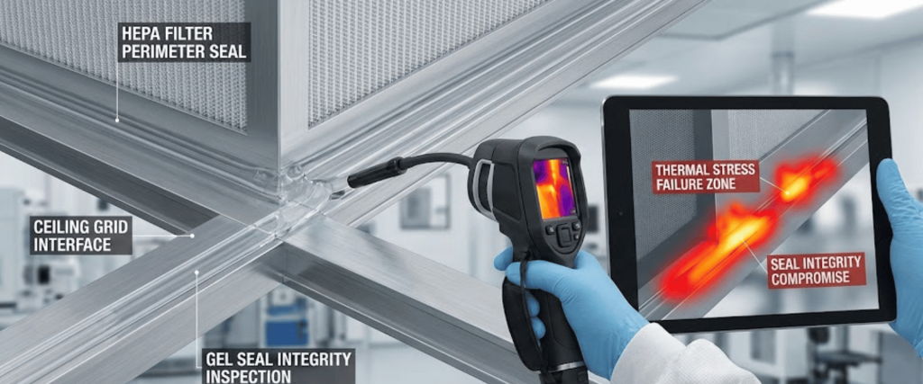
However, in high-temperature applications (up to 260°C or higher), the thermal expansion of the filter housing, sealant, and media can create bypass leaks. Verifying that the filter performs as rated after thermal cycling is critical.
Testing PTFE filters is not identical to testing glass filters. Facility managers often encounter false failures due to the physics of PTFE membranes.
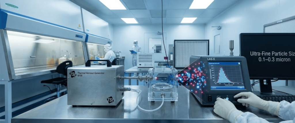
Standard integrity testing often uses a thermal aerosol generator (producing particles via heat).
PTFE is a surface-loading media, unlike glass fiber, which is depth-loading.
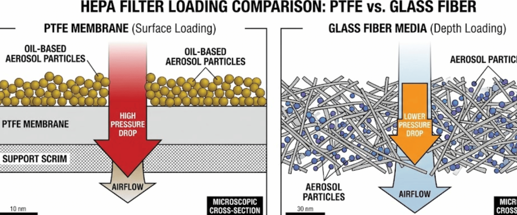
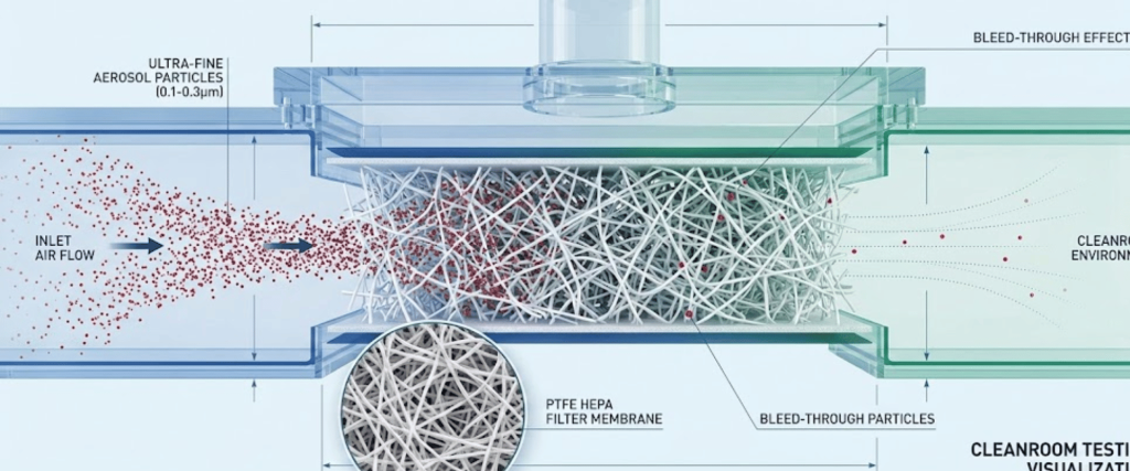
High concentrations of oil-based aerosols (like PAO) used for standard photometry can rapidly clog PTFE pores, permanently increasing pressure drop and ruining the filter during the test itself.
To ensure valid results without damaging the filtration media, specific protocols must be adopted for PTFE in high-temperature environments.
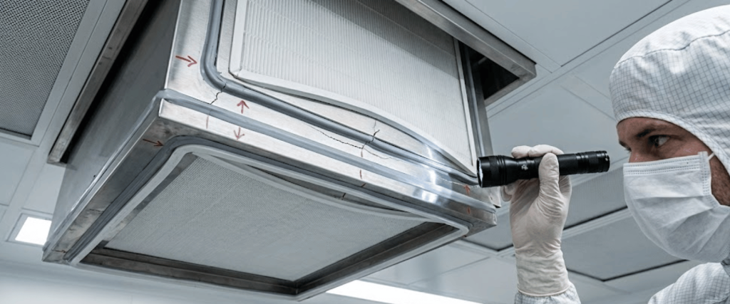
Before introducing any aerosol, inspect the gel seal (often silicone or polyurethane for high heat) and the gasket. High temperatures cause expansion and contraction cycles that can delaminate the media from the frame.
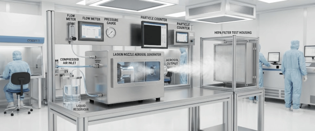
For PTFE, Laskin Nozzle (Cold) generation is often preferred over thermal generation.
This is the most critical decision in the verification process.
| Avoid PTFE if possible | Photometer | Discrete Particle Counter (DPC) |
|---|---|---|
| Concentration | Requires high concentration (10–20 µg/L) | Works at ultra‑low concentration (<1 µg/L) |
| Risk to PTFE | High (rapid loading / clogging) | Low (safe for PTFE) |
| Sensitivity | Measures total mass penetration | Counts individual leaks |
| Verdict | Avoid for PTFE if possible | Recommended for PTFE |
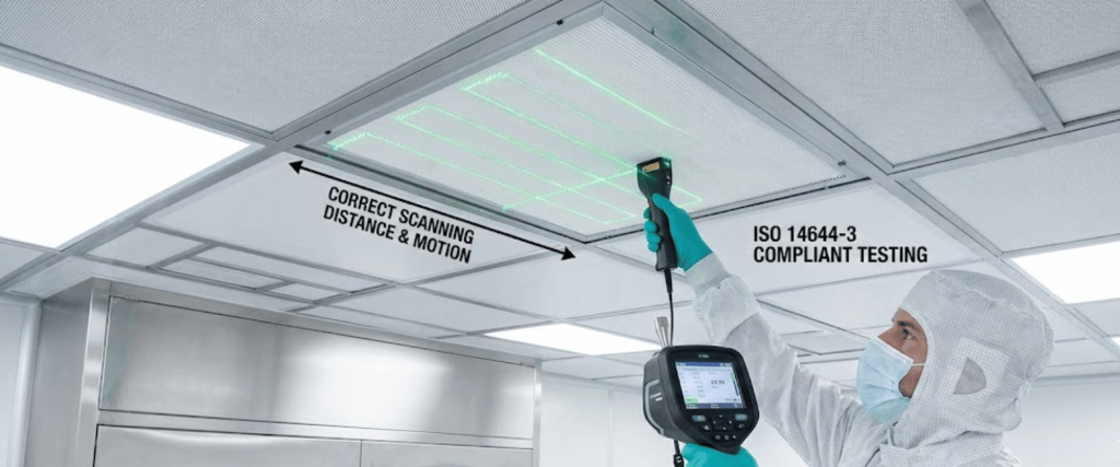
Your verification process must document compliance with the following.
Note on Temperature: While the filters operate at high temperatures, integrity testing is almost always performed at ambient temperatures during maintenance shutdowns. Testing at 250°C is hazardous and technically infeasible for most standard equipment.
Verifying the integrity of PTFE HEPA filters in high-temperature cleanrooms requires a deviation from standard glass-filter protocols.
By switching to Discrete Particle Counters to lower aerosol concentration and utilizing Laskin nozzle generation to avoid bleed-through, facility managers can prevent false failures and extend the life of their filtration systems.
Prioritize the perimeter seal inspection, as thermal cycling is the primary enemy of high-temperature filter integrity.
PTFE filters are preferred because they are chemically inert and boron-free, preventing off-gassing that can damage semiconductor wafers. They also offer higher mechanical strength and a lower pressure drop compared to fragile glass fiber media.
Bleed-through occurs when thermal aerosol particles are so small that they naturally pass through the PTFE membrane without it being a leak. This often leads to false failures during photometer testing, causing unnecessary filter replacement.
A photometer requires high aerosol concentrations that can quickly clog (load) the delicate PTFE membrane. A DPC is safer because it uses ultra-low aerosol concentrations to detect leaks without damaging the filter lifespan.
No. Although these filters operate in high-heat zones (up to 260°C), integrity testing should always be performed at ambient temperature during a maintenance shutdown to ensure operator safety and equipment accuracy.