In the highly regulated world of pharmaceutical manufacturing and aseptic processing, maintaining a sterile environment is not just a goal; it is a strict requirement.
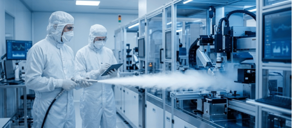
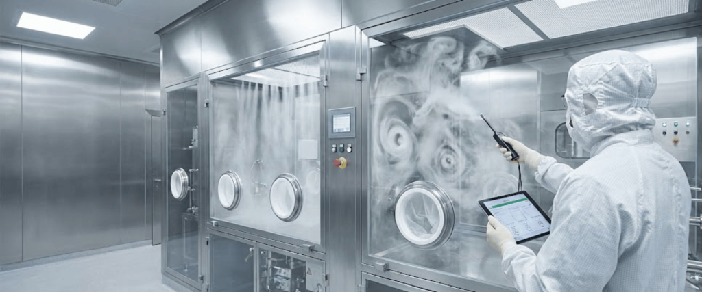
Restricted Access Barrier Systems (RABS) and Isolators are at the frontline of contamination control, physically separating operators from critical process zones.
However, the physical barrier is only half the equation. The other half is the aerodynamic barrier provided by unidirectional airflow (often referred to as laminar flow).
Assessing airflow velocity uniformity in these systems is a critical validation step to ensure that the environment remains free of viable and non-viable particulates.
This guide breaks down why this assessment is essential, the regulatory expectations, and the methodology for executing it effectively.
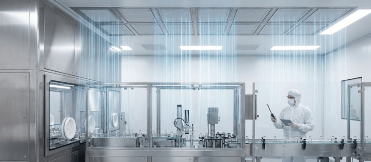
Airflow velocity uniformity refers to the consistency of the speed at which filtered air moves through a critical zone (typically a Grade A / ISO 5 environment). In RABS and isolators, High-Efficiency Particulate Air (HEPA) or Ultra-Low Penetration Air (ULPA) filters push a continuous, unidirectional stream of air downward over the process area.

The goal is to sweep any potential contaminants away from the product and out through the exhaust or return ducts. If the airflow is too fast, it can create turbulence; if it is too slow, it may fail to clear particles or allow ambient air to ingress. Uniformity ensures there are no dead zones or turbulent eddies where contaminants could linger.
Global regulatory bodies dictate specific parameters for airflow in critical zones.

The revised EU GMP Annex 1 and FDA guidelines for sterile drug products explicitly state that Grade A environments must maintain a unidirectional airflow with a target velocity.
The primary intent of uniform airflow is the First Air principle. First air is the filtered, particle-free air that exits the HEPA filter and hits the product or critical surface first, before encountering any operators or equipment.
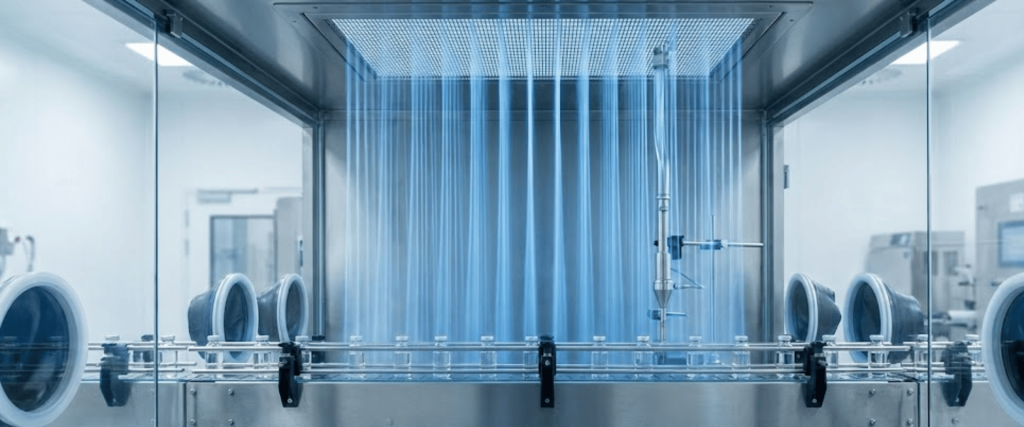
Uniform velocity ensures that this first air remains undisturbed and provides a protective curtain over the sterile product.
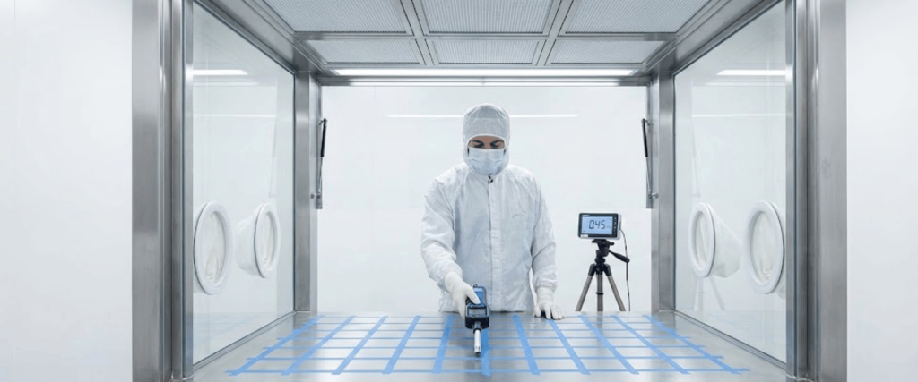
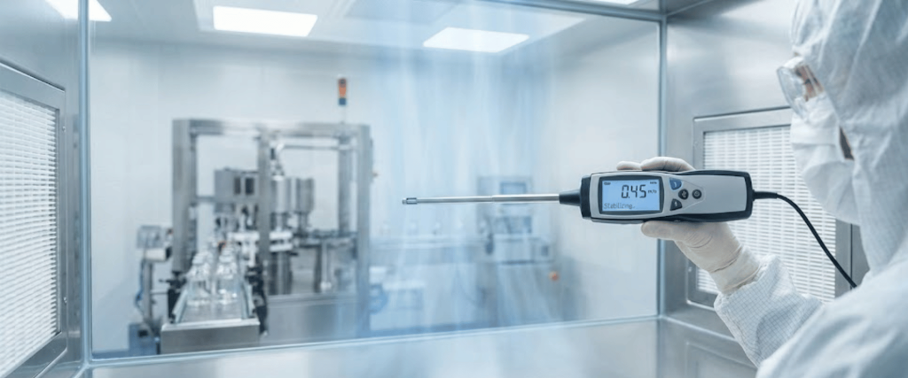
Validating airflow velocity uniformity requires precise instrumentation and a systematic approach. Here is the standard methodology used by validation engineers.
Before turning on the testing equipment, the measurement plane must be defined.
Note: Ensure all probes are recently calibrated and sterilized/sanitized before being introduced into the RABS or Isolator.
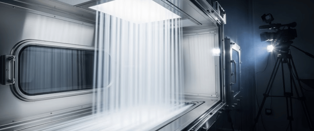
Velocity numbers on a spreadsheet are not enough. Regulators require qualitative, visual proof that the airflow is uniform and sweeping away contaminants.
While the principles of airflow testing are similar for both systems, their structural differences influence how air behaves.
| System Type | Aerodynamic Characteristics | Assessment Considerations |
|---|---|---|
| Active RABS | Uses onboard fans and HEPA filters. Air is often exhausted into the surrounding Grade B cleanroom. | Airflow velocity must be carefully balanced to avoid turbulent mixing at the interface where RABS air meets cleanroom air. |
| Isolator | Fully enclosed and sealed system. Air is recirculated internally or exhausted completely to the outside. | Very sensitive to pressure differences. Detailed internal airflow mapping is critical, as the closed enclosure can easily develop turbulence if airflow velocities are not properly matched. |
If your velocity assessment fails or shows poor uniformity, consider the following common culprits.
Assessing airflow velocity uniformity in RABS and Isolator systems is fundamental to the safety and efficacy of sterile manufacturing.
By strictly adhering to grid-based velocity measurements and validating those numbers with comprehensive smoke studies, manufacturers can ensure they are meeting regulatory standards like EU GMP Annex 1 and, most importantly, protecting the end patient from contamination risks.
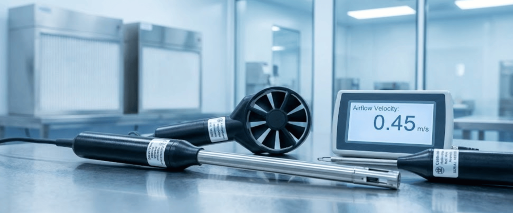
The widely accepted industry standard, in alignment with EU GMP Annex 1, is a continuous unidirectional airflow velocity of 0.45 m/s (90 fpm) at the working height, with an acceptable variance of ±20%.
Velocity numbers only tell you the speed of the air. Regulatory bodies require smoke studies (airflow visualization) to visually prove that the air is actually moving smoothly without turbulence and effectively sweeping contaminants away from the sterile product.
Uneven airflow is typically caused by aging or locally blocked HEPA filters, poor placement of bulky equipment that obstructs the air path, or an imbalance in the system’s return or exhaust ducts.