
Polarized light microscopy serves as a foundational analytical technique across crystallography, materials science, pharmaceutical solid-state characterization, and clinical pathology.
Accurate identification of anisotropic structures relies entirely on one physical condition: complete optical extinction when polarizers are crossed at 90 degrees.
Technicians and researchers frequently encounter optical artifacts that mimic sample birefringence.
Unwanted light leakage, asymmetric halos, and gray background haze obscure subtle phase boundaries, turning routine crystal identification or synovial fluid analysis into guesswork.
Eliminating these optical distortions requires understanding the mechanical and optical origins of depolarization, followed by methodical hardware calibration.
Optical Physics Behind Extinction and False Birefringence
Optical extinction occurs when linearly polarized light vibrating in one plane encounters an analyzer oriented strictly perpendicular (90 degrees) to that plane.
When observing an optically isotropic medium, such as air, water, or cubic crystals, the vibrational direction of the light remains unaltered, allowing no light to traverse the analyzer. The resulting field of view appears completely black.
Anisotropic materials possess directional variations in refractive index ($n_e – n_o$), splitting the incident ray into two orthogonal wavefronts: the ordinary ($O$) ray and extraordinary ($E$) ray.
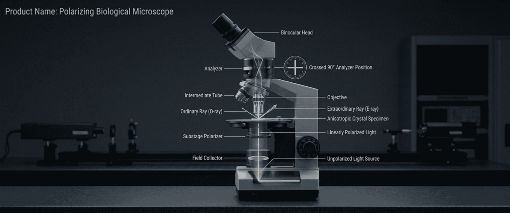
Because these rays travel at different phase velocities, they exit the specimen with a phase lag known as optical retardation ($\Gamma$).
Recombining these wavefronts at the analyzer produces constructive and destructive interference, generating the characteristic interference colors cataloged on the Michel-Lévy chart.
Differentiating Stress Depolarization from True Crystallographic Retardation
False birefringence happens when non-crystalline components within the optical path alter the polarization state of light before or after it interacts with the specimen. Stress birefringence in optical glass, misaligned polarizers, and reflections from metal surfaces introduce unintended phase shifts.
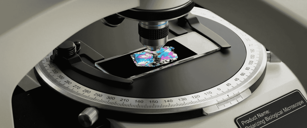
True crystallographic birefringence rotates with the specimen: turning the circular stage 360 degrees yields four distinct positions of maximum brightness and four extinction positions spaced exactly 90 degrees apart. Conversely, false birefringence caused by strained objectives or condenser lenses remains stationary regardless of stage rotation, creating persistent illumination across the field.
Primary Causes of Background Leakage and Extinction Breakdown
Achieving a high extinction ratio requires an unobstructed, stress-free optical train. Several mechanical and optical faults commonly degrade this setup.
1) Objective Glass Strain and Thermal Mounting Stress
Standard achromatic and plan-achromatic objectives contain optical elements secured in brass or aluminum barrels using mechanical retaining rings or optical adhesives. Thermal cycling, mechanical drops, or overtightened retaining collars introduce internal mechanical stress into the glass elements.
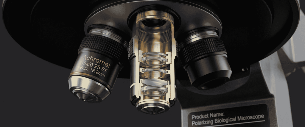
Stressed glass exhibits photoelasticity, acquiring localized refractive index variations that split polarized light into elliptical wavefronts. This causes depolarization, producing a dull gray or bluish background instead of deep optical extinction. Dedicated polarized light investigations require strain-free objectives, marked specifically with red or white engravings denoting specialized low-strain glass selection and relaxed mounting tolerances.
2) Substage Condenser Misalignment and Aperture Glare
Substage Abbe condensers equipped with high numerical apertures (NA) collect light across broad angular geometries. Highly oblique rays striking curved lens surfaces undergo differential reflection and refraction according to Fresnel formulas, causing slight depolarization known as rotation of the vibration plane.
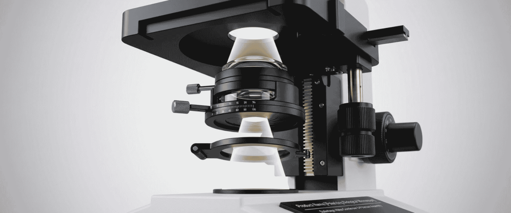
Opening the condenser iris diaphragm beyond 70–80% of the objective’s rear aperture floods the optical path with high-angle rays, washing out extinction contrast. Condenser lenses that have developed internal cement separation or structural strain similarly scatter light into the dark field.
3) Polarizer and Analyzer Angular Deviation
Commercial polarizing microscopes utilize a linear polarizer positioned below the condenser and a rotatable analyzer located above the nosepiece. Extinction requires the vibration axes to cross at precisely $90^\circ \pm 0.1^\circ$.
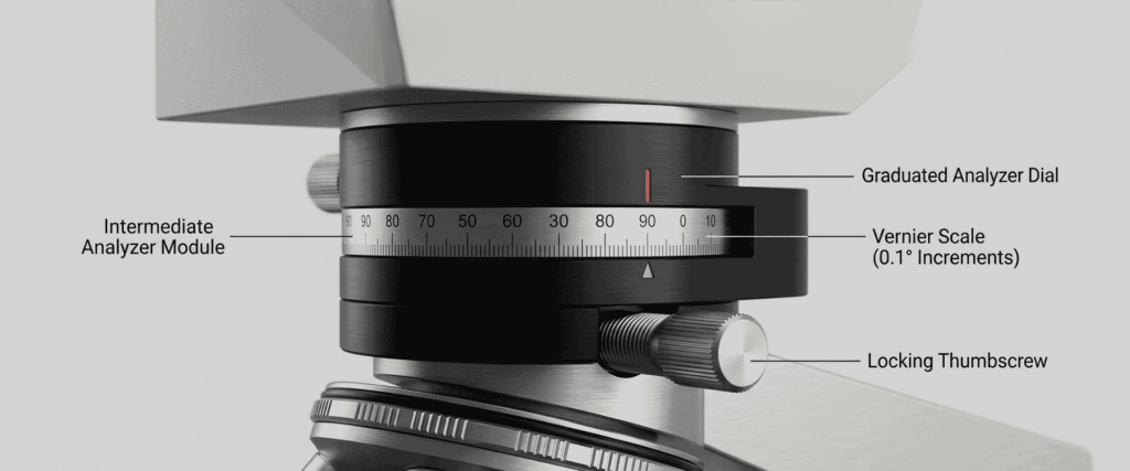
Wear on detent mechanisms, loose thumbscrews, or manual adjustment errors readily produce angular offsets. A misalignment of only 2 to 3 degrees increases background illumination by orders of magnitude, washing out low-order first-class gray retardation details common in thin biological sections and microcrystalline precipitates.
Diagnostic and Calibration Workflow for Crossed-Polar Systems
Restoring full optical extinction and reliable crystal analysis requires a systematic hardware setup procedure.
Calibrating the $0^\circ\text{–}90^\circ$ Analyzer and Field Polarizer
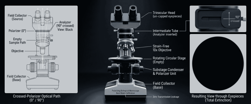
- Clear the Optical Train: Remove all slides, specimen holders, retardation plates ($\lambda$, $1/4\lambda$, quartz wedge), and swing the Bertrand lens out of the path.
- Align Polarizer Orientation: Set the substage polarizer to its fixed zero index (commonly aligned East-West or North-South depending on laboratory standard).
- Engage the Analyzer: Slide the intermediate analyzer into the optical path.
- Locate Minimum Transmission: Slowly adjust the analyzer dial around the 90-degree index while viewing through the eyepieces. Adjust brightness until the field transitions from dark gray to complete optical black. Lock the vernier or clamping screw at the absolute minimum point.
Verifying Conoscopic Optical Figures with the Bertrand Lens
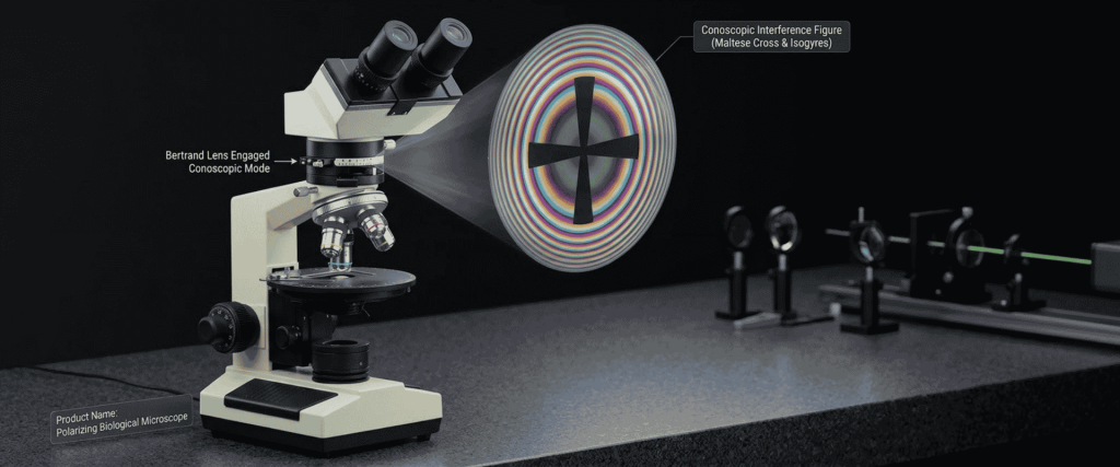
Conoscopic observation analyzes the objective’s back focal plane, mapping directional wave behavior rather than spatial specimen morphology.
- Focus on a clear slide using a medium-to-high magnification strain-free objective ($10\times$ or $40\times$).
- Insert the Bertrand lens into the light path or remove an eyepiece and inspect the tube with a phase centering telescope.
- Observe the back focal plane under crossed polars without a specimen. A properly aligned, strain-free system reveals a centered, sharp black Maltese cross (isogyres).
- Distorted, split, or displaced isogyres in an empty field confirm optical strain or lens decentering within the objective or condenser elements.
Aligning Center-Adjustable Nosepieces for Parcentric Rotation
Rotating specimens on a 360-degree graduated circular stage allows users to track extinction angles and pleochroism.
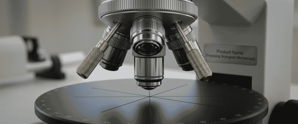
When an objective is not coaxial with the stage’s physical axis of rotation, the target crystal sweeps out of the field of view during rotation.
- Place a crosshair calibration slide or small reference crystal under the crosshair reticle eyepiece.
- Rotate the stage 180 degrees and observe the path taken by the reference point.
- Insert two centering keys into the center-adjustable quadruple nosepiece sockets above the objective.
- Adjust the centering screws to translate the image point halfway back toward the center of the eyepiece crosshairs.
- Translate the slide manually to center the feature, then repeat the 180-degree rotation until the target remains centered throughout a full 360-degree rotation.
Technical Comparison of Optical Extinction Failures and Corrective Actions
| Defect / Problem | Observable Symptom | Root Cause | Corrective Protocol |
| Glass Strain Birefringence | Static bright spots or cross-like haze that do not rotate with the stage | Mechanical stress inside non-strain-free objective or condenser glass | Replace with dedicated strain-free achromatic objectives; inspect condenser mounting rings |
| Angular Polarizer Offset | Field appears dark gray instead of black; loss of first-order white/gray | Polarizer and analyzer axes deviate from a true 90-degree orthogonal relationship | Recalibrate analyzer angle to minimum photometric transmission using bare-beam setting |
| Aperture Depolarization | Curved extinction shadows; edge brightness at high magnifications | Condenser numerical aperture set too wide, creating steep incident angles | Stop down the condenser aperture diaphragm to approximately 70% of the objective pupil |
| Parcentricity Drift | Specimen sweeps out of view when rotating stage to check extinction angles | Objective optical axis is misaligned relative to the stage’s mechanical rotation center | Use nosepiece centering keys to center the objective axis to the crosshair reticle |
| Retardation Misinterpretation | Inconsistent sign of elongation (+/-) during crystal identification | Compensator plate inserted backwards or slow axis ($\gamma$) orientation unknown | Verify $\lambda$ slip slow-axis orientation ($45^\circ$) against known standard mineral (e.g., quartz) |
| Cover Glass Birefringence | Irregular, patchy bright fields appearing only when slide is placed on stage | Plastic cover slips, thick commercial slide glass, or mounting media shrinkage | Switch to high-quality #1.5 optical glass coverslips and low-birefringence mounting resins |
Role of Retardation Compensators in Verifying True Anisotropy
Resolving weak birefringence requires optical path difference enhancement using calibrated compensator plates inserted into the $45^\circ$ accessory slot located between the objective and analyzer:
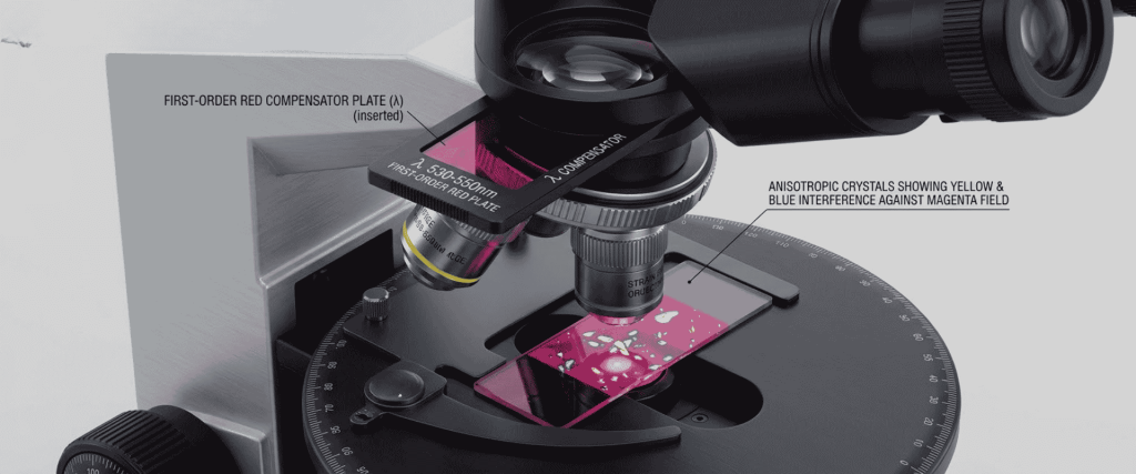
$\lambda$ Slip (First-Class Red / Tint Plate, ~530–550 nm)
Shifts the entire background from black to a magenta-red (first-order red). Weakly birefringent biological specimens or micro-crystals that only display subtle gray shades under standard crossed polars shift decisively into distinct second-order blue or first-order yellow interference colors, pinpointing fast and slow vibration axes.
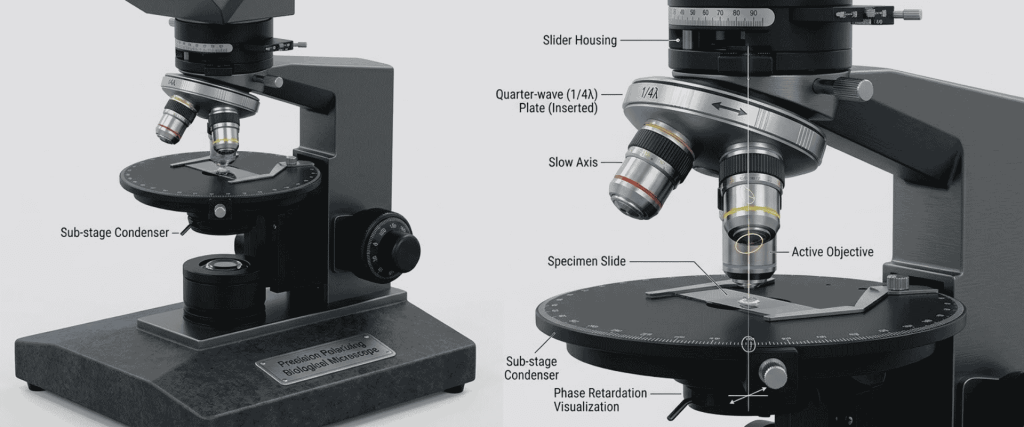
$1/4\lambda$ Slip (Quarter-Wave Plate, ~137–150 nm)
Converts linearly polarized light into elliptically or circularly polarized light, facilitating precise measurement of fractional fringe shifts and small retardation values.
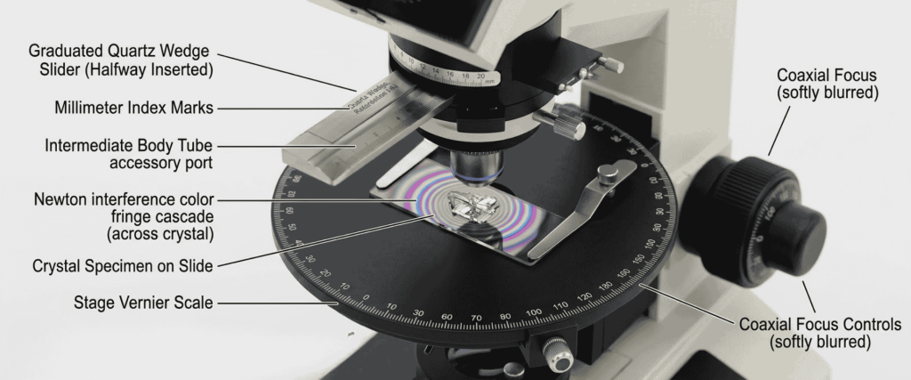
Quartz Wedge
Features a continuously variable thickness producing multiple orders of interference colors, allowing direct counting of fringe orders to calculate precise sample thickness or refractive index variance.
Hardware Precision in the BMP-107 Polarizing Microscope Series
Research facilities requiring dependable optical extinction across clinical and industrial workflows rely on specialized platforms like the Polarizing Biological Microscope from us.
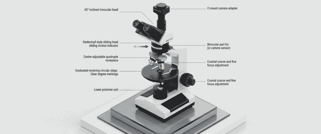
Available in binocular (BMP-107B) and trinocular (BMP-107T) configurations, this platform incorporates the mechanical features necessary to resolve false birefringence:
- Strain-Free Achromatic Objectives ($4\times$, $10\times$, $40\times$): Engineered specifically to eliminate internal glass stress, maintaining high extinction ratios across wide magnification ranges.
- Center-Adjustable Quadruple Nosepiece: Each objective port includes independent adjustment screws to secure true parcentric alignment across stage rotations.
- Revolving Round Stage ($\Phi 160\text{ mm}$): Features full 360-degree rotation with $1^\circ$ graduations and a precision Vernier scale delivering $6’$ (arcminute) reading resolution for angular extinction measurements.
- Integrated Conoscopic Suite: Features a slide-in/slide-out Bertrand lens and a full complement of optical compensators ($\lambda$ plate, $1/4\lambda$ plate, and quartz wedge).
- Trinocular Documentation Pathway (BMP-107T): Provides an independent optical path for digital imaging sensors, facilitating photomicrography without disturbing visual polarization alignment.
Explore broader cleanroom, metrology, and laboratory solutions across the Applied Physics USA catalog and review regulatory guides in the Applied Physics Publications directory.
Conclusion
False birefringence and extinction failures compromise the integrity of crystallographic, metallurgical, and biological evaluations.
Background illumination leaks mask low-retardation phases, while stage misalignments introduce measurement error during extinction angle logging.
Maintaining defensible polarized light data requires regular calibration routines: confirming true crossed-polar extinction, adjusting condenser aperture geometry, verifying optical figures via the Bertrand lens, and utilizing strain-free optics.
Investing in hardware built with center-adjustable nosepieces, precision Vernier rotating stages, and dedicated retardation compensators ensures consistent optical clarity across demanding research environments.
Frequently Asked Questions (FAQs)
1. Why does the background appear dark gray instead of pure black under crossed polars?
Incomplete extinction typically occurs when the analyzer and polarizer deviate from a true 90-degree orthogonal orientation. It also happens when the substage condenser aperture is left completely open, flooding the light path with steep, depolarizing rays, or when using standard non-strain-free objectives containing mechanical glass stress.
2. How can a microscopist distinguish sample birefringence from optical system strain?
Rotate the circular stage through 360 degrees while watching the target feature. Real specimen birefringence alternates between four bright illumination peaks and four extinction positions spaced exactly 90 degrees apart. Optical artifacts caused by strained lenses or condenser elements stay stationary regardless of stage movement.
3. What makes strain-free objectives necessary for polarized light microscopy?
Standard biological objectives use metal retaining rings and adhesive bonds that compress the internal glass elements. This mechanical pressure induces photoelastic stress, causing the glass to split polarized light and create background glare. Strain-free objectives use specialized optical glass assembled in relaxed, tension-free mounts to preserve complete dark-field extinction.
4. How does a center-adjustable nosepiece eliminate parcentricity drift?
Standard nosepieces lack individual axis alignment, causing small specimens to sweep out of view as the circular stage turns. A center-adjustable nosepiece provides independent centering screws for each objective port. This allows the optical center of each lens to be aligned with the mechanical rotation axis of the stage.
5. When should the Bertrand lens be engaged in the optical path?
Engage the Bertrand lens for conoscopic analysis to inspect the objective’s rear focal plane rather than the specimen surface. This produces interference figures (isogyres and melatopes), which are required to determine whether a crystal is uniaxial or biaxial and whether its optical sign is positive or negative.
