Cleanroom engineer in bunny-hood protective suit operating plasma chamber with glowing purple ring and monitoring screens

Implementing Closed-Loop Process Control in Sputter Deposition Systems

Sputter deposition is the backbone of modern semiconductor and coating industries, used to create everything from optical filters to conductive layers on touchscreens.

While DC sputtering of metals is relatively straightforward, reactive sputtering, adding a reactive gas like oxygen or nitrogen to form a compound,s introduces significant instability.

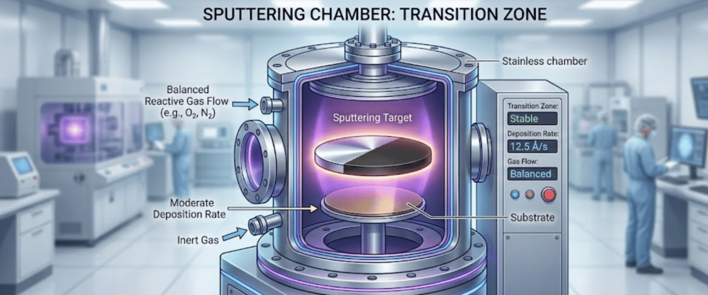
To maintain high deposition rates and stoichiometric precision, manufacturers must operate in the unstable transition region of the process.

This requires moving beyond fixed gas flow settings and implementing Closed Loop Process Control (CLPC).

The Challenge: The Hysteresis Effect

The primary reason for implementing closed-loop control is the Hysteresis Effect. When a reactive gas is introduced to the chamber, the process does not behave linearly.

Graph showing reactive sputtering hysteresis curve with metallic, transition, and poisoned modes, plus sputtering chamber illustration

Metallic vs. Poisoned Mode

Metallic Mode

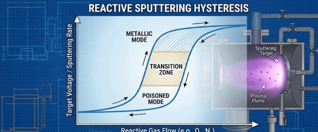
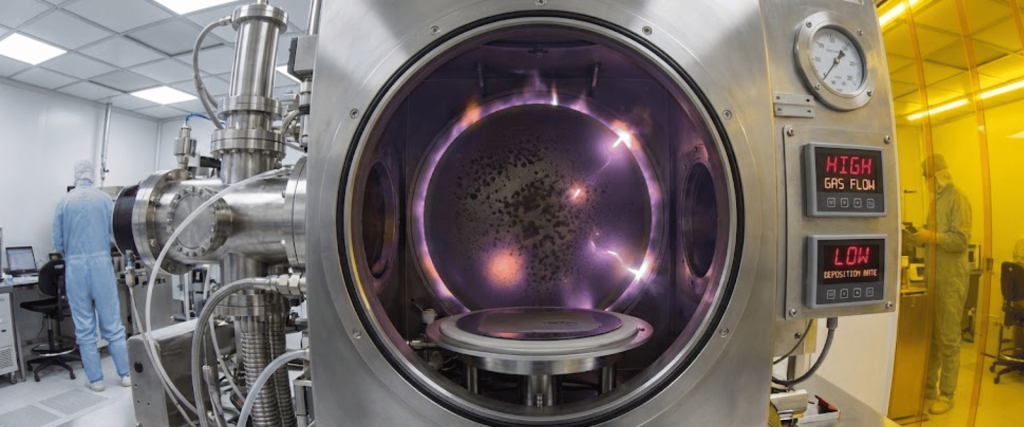
At low gas flows, the target remains metallic. Sputtering is fast, but the film on the substrate may not fully oxidize/nitride, leading to poor optical or electrical properties.

Plasma jet testing in a stainless-steel vacuum chamber, glowing purple-orange plume emitted between circular electrode ports

Poisoned Mode

If the gas flow is too high, the reactive gas reacts with the target surface, forming an insulating compound layer. This poisons the target, causing the deposition rate to plummet and often leading to arcing.

Cleanroom technicians in suits work around a stainless vacuum chamber with glowing plasma inside and control panels showing gas flow and deposition

The Transition Zone

The ideal operating point is often right between these two modes. However, due to the hysteresis curve, you cannot maintain this point with a constant gas flow (open-loop control); the system will naturally drift into either the metallic or poisoned state.

Sputtering chamber cross-section showing target, substrate, glowing plasma, gas flow labels, control panel, and lab technicians in cleanroom

Strategies for Closed-Loop Control

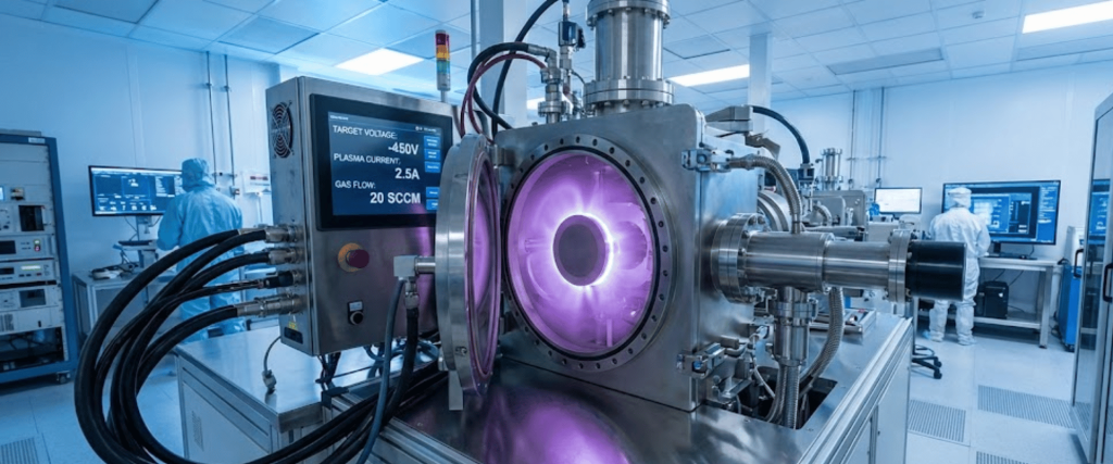
To stabilize the process in the transition zone, the system must actively adjust the reactive gas flow in real-time based on feedback from the plasma. There are two primary methods for achieving this.

Plasma Emission Monitoring (PEM)

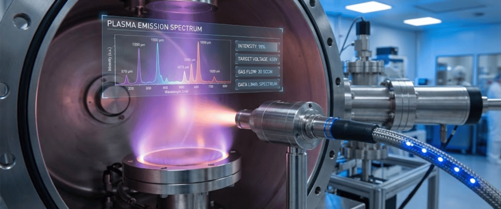
PEM is the most common and generally the most responsive method for insulating films.

Plasma emission test in a lab vacuum chamber showing purple-blue plasma, diagnostic probe, spectrum overlay, and stainless steel equipment
  • How it works: An optical sensor (collimator and fiber optic cable) points at the plasma discharge near the target. It filters for a specific wavelength of light emitted by the sputtering metal (e.g., Aluminum or Titanium).
  • The Feedback Loop: As the target gets poisoned by the reactive gas, the metal emission intensity drops. A PID controller detects this drop and instantly reduces the reactive gas flow to bring the metal intensity back to the setpoint.
  • Pros: Highly sensitive to changes in target condition; direct measurement of the plasma species.

Target Voltage/Impedance Control

  • How it works: This method monitors the discharge voltage of the cathode. As the target surface changes from metal to compound, the secondary electron emission coefficient changes, altering the discharge voltage.
  • The Feedback Loop: The controller adjusts the gas flow to maintain a specific target voltage.
  • Pros: Requires no optical windows (which can get coated and cloud up); robust for certain materials like Aluminum Oxide.
A cleanroom lab with technicians and a stainless steel vacuum chamber emitting a glowing purple plasma for semiconductor processing

Step-by-Step Implementation Process

Step 1: Baseline Characterization

Before automating, you must map the system manually.

A scientist in a rabbit-suit operates controls inside a high-tech lab with a glowing plasma chamber, monitors, and labeled equipment

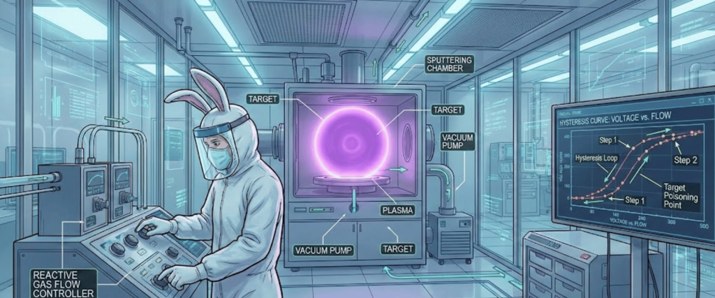
Run the process with fixed gas flows, increasing the reactive gas step-by-step until the target poisons, then decreasing it until it returns to metallic mode. Plot these points to visualize your specific hysteresis loop.

Step 2: Hardware Integration

  • Gas Delivery: Replace standard needle valves or slow Mass Flow Controllers (MFCs) with fast-response Piezo valves or specialized high-speed MFCs. Standard thermal MFCs are often too slow (settling times >1 second) to catch the process before it flips modes.
  • Controller: Install a PID controller capable of sub-millisecond processing loops.
Technician in blue cleanroom suit and gloves adjusting gauges and wiring on stainless-steel pharmaceutical processing equipment

Step 3: PID Tuning

Tuning the Proportional-Integral-Derivative (PID) loop is critical.

Technician in cleanroom suit operating a touchscreen control panel next to a plasma chamber emitting purple light
  • Proportional (P): Provides the immediate reaction to error. If too high, the gas flow will oscillate wildly (ringing).
  • Integral (I): Corrects steady-state error.
  • Derivative (D): Predicts future error. (Often set to zero in sputtering applications to avoid amplifying noise).

Benefits of Closed-Loop Systems

Implementing a robust CLPC system offers immediate ROI for high-volume manufacturing.

  • Higher Deposition Rates: You can operate right on the knee of the curve, often achieving rates 5x–10x higher than fully poisoned mode.
  • Film Consistency: Ensures uniform stoichiometry layer-to-layer and run-to-run.
  • Arc Suppression: By preventing the target from becoming fully insulating, you reduce the likelihood of micro-arcs that generate particles and defects.

Conclusion

Moving from open-loop to closed-loop process control is a necessary evolution for precision thin-film manufacturing.

While it requires an upfront investment in fast-response valves and sensing hardware (PEM or Voltage), the ability to stabilize the reactive sputtering process in the high-rate transition zone significantly reduces cycle times and improves film quality.

Frequently Asked Questions (FAQs)

1. Why is closed-loop control necessary in sputtering?

It stabilizes the transition zone, allowing for much higher deposition rates and more consistent film quality than manual gas control.

2. How does the hysteresis effect impact the process?

It causes the system to jump uncontrollably between metallic and poisoned modes, making it impossible to maintain a steady state without active feedback.

3. What is the difference between PEM and Voltage control?

PEM uses optical sensors to monitor plasma light intensity, while Voltage control monitors the cathode’s electrical discharge to regulate gas flow.

4. Why are fast-response Piezo valves required?

Standard valves are too slow; Piezo valves react in milliseconds to prevent the process from drifting into the poisoned mode.

Leave a Reply

Your email address will not be published. Required fields are marked *

Related Posts

About Applied Physics USA

Since 1992, Applied Physics Corporation has been a leading global provider of precision contamination control and metrology standards. We specialize in airflow visualization, particle size standards, and cleanroom decontamination solutions for critical environments.

Trending Articles