
In Surface Mount Technology (SMT), the reflow soldering process is the most critical stage for ensuring electrical and mechanical integrity.
As components become smaller (01005 and 008004 packages) and PCBs become more complex with varying copper weights, the margin for error in temperature control has vanished.
Thermal non-uniformity, the variance in temperature across different points of a PCB or across the oven’s heating zones, is a primary driver of assembly defects.
Thermal non-uniformity occurs when heat transfer is inconsistent across the process width or along the conveyor length. In a reflow oven, heat is typically transferred via forced convection.
Factors contributing to non-uniformity include.
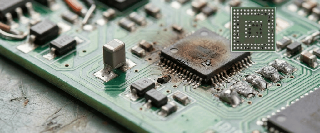
When thermal uniformity is not maintained within a tight tolerance (typically ±2°C across the board), several high-cost defects occur.
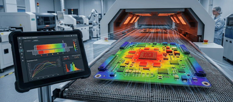
To mitigate these risks, manufacturers are moving beyond basic pass/fail profiling toward advanced diagnostics.
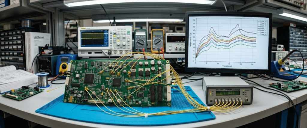
Modern diagnostics utilize multi-channel data loggers (up to 12 or more thermocouples) to map the Delta T across the entire assembly. This provides a granular view of how different thermal masses absorb heat.
Advanced systems now measure the actual airflow pressure and velocity within the oven.

Since convection is the primary heat transfer mechanism, monitoring the health of the blower motors and the consistency of the air delivery system is vital for predictive maintenance.
Engineering teams are increasingly using CFD to simulate airflow inside the reflow chamber.
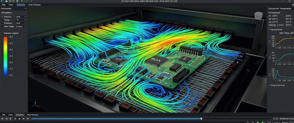
This enables optimization of nozzle designs and zone configurations before a physical board is even processed, reducing the time required for manual profile dial-in.
Modern diagnostic software automatically calculates the Process Capability Index (CPK).
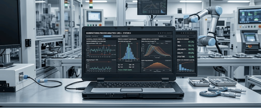
This statistical tool measures how well the oven’s thermal performance fits within the specific process window of a given solder paste chemistry.
To ensure long-term stability in a production environment, facilities should implement the following.
As the electronics industry pushes toward higher densities and lead-free alloys with narrower process windows, the ability to diagnose and correct thermal non-uniformity is no longer optional.
By employing advanced profiling and real-time monitoring, manufacturers can transition from reactive defect management to proactive process excellence, ensuring maximum yield and long-term product reliability.
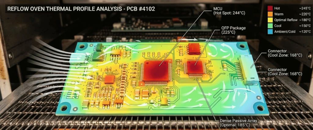
Thermal non-uniformity refers to inconsistent temperature distribution across the PCB or the oven’s heating zones. It occurs when different areas of a circuit board heat up at different rates, often caused by irregular airflow, shadowing from tall components, or varying copper densities on the board.
When heat is not distributed evenly, it leads to several SMT assembly failures. The most common issues include tombstoning (where components stand upright), cold solder joints (due to insufficient melting), and voiding, which compromises the mechanical strength of the connection.
Delta T (the difference between the hottest and coldest points on a board) is measured using multi-channel thermal profilers. By attaching multiple thermocouples to different thermal masses on the PCB, engineers can map the exact temperature variance and adjust the oven’s zones to bring the board within the required process window.
To ensure long-term thermal stability, facilities should perform weekly machine-only profiles to detect any drift in heating elements. Regular maintenance, such as cleaning flux residue from airflow nozzles and verifying conveyor speed, is also essential for preventing non-uniformity in high-volume production.