Step-by-Step: Setting Up an Automatic SMT Stencil Printer for Your PCB Production Line
Before a single component is placed on your PCB, one process quietly determines whether your entire batch passes or fails: solder paste printing.
A misaligned print, wrong squeegee pressure, or a skipped cleaning cycle can send hundreds of boards straight to rework.
The automatic SMT stencil printer solves all of that, but only when you set it up the right way. This guide walks you through every step, so your production line runs clean, accurate, and consistent from the very first board.
What Is an Automatic SMT Stencil Printer?
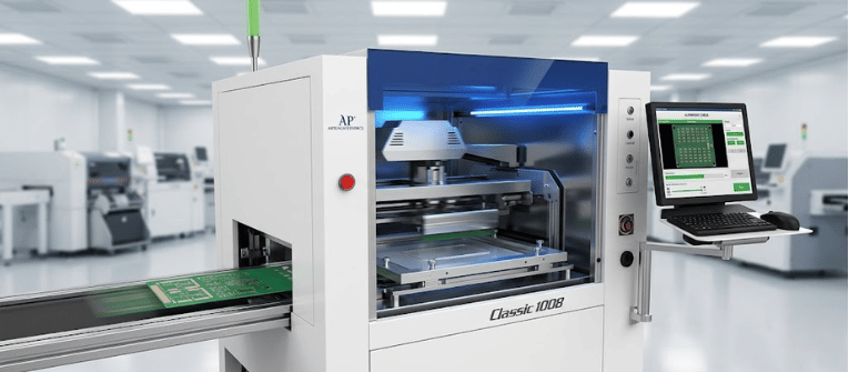
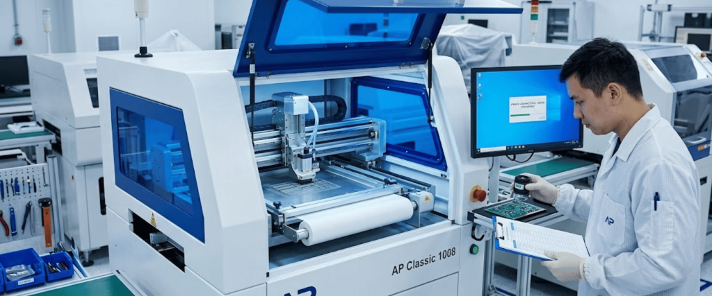
An automatic SMT stencil printer is a precision machine used at the very beginning of a Surface Mount Technology (SMT) assembly line.
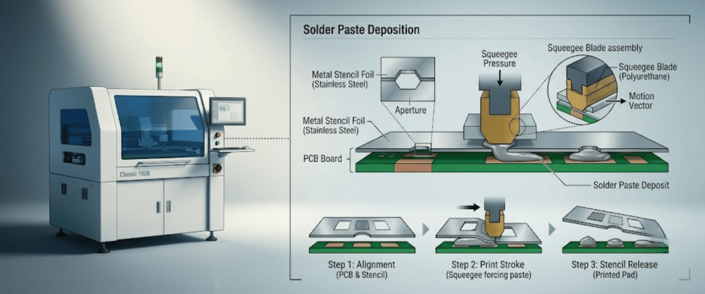
Its main job is to deposit a consistent and measured amount of solder paste onto the PCB pads through a metal stencil before components are placed.
Compared to semi-automatic or manual printers, which require operator input for alignment and squeegee movement, a fully automatic stencil printer handles everything by itself.
It uses optical vision systems, servo motors, and programmable parameters to ensure accurate and repeatable solder paste printing.
Why Proper Setup Matters More Than You Think
A poorly set-up printer doesn’t announce itself immediately. You might run 50 boards before bridging, paste collapse, or misalignment shows up in inspection.
By that point, the cost in rework time, materials, and production downtime adds up fast.
The printing process accounts for roughly 60–70% of all SMT assembly defects, more than pick-and-place and reflow combined.
This means the stencil printer is your first and most critical line of defense for quality control. Getting each setup step right ensures you’re protecting everything downstream.
What You Need Before You Start
Before powering on the machine, gather and verify the following.
PCB boards: Econfirm model, revision, and ensure that the boards are clean and dry.
Solder stencil: Matched to the exact PCB revision; check for tension and open apertures.
Solder paste: Correct alloy type (lead-free or leaded), proper viscosity for your stencil thickness.
Support pins (thimbles): Sized and positioned to match the PCB layout.
Machine manual: Reference for machine-specific parameters and error codes.
Solder paste that has been refrigerated must be warmed to room temperature (approximately 25°C) and stirred for 2–3 minutes before use to ensure uniform flux distribution.
Step-by-Step Setup Process
1) Machine Inspection and Power-On
Before starting production, perform a pre-operation check.
Confirm that the power supply and air pressure supply are both connected and at the correct levels.
Remove any transport-fixing blocks on the machine axes; a new machine will have these installed to protect the axes during shipping.
Power on the machine and allow it to complete its return-to-origin (homing) sequence
Stay clear of moving parts during homing; keep your hands outside the machine until the axes lock into home position.
Clean the work table surface with a lint-free cloth and IPA; no paste residue, dust, or foreign material should remain.
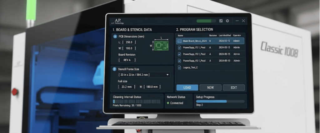
2) Create or Load a Program
Modern automatic SMT printers use stored programs for each PCB type. Either load an existing program or create a new one.
Cleaning interval: How frequently the stencil underside should be cleaned (e.g., every 5 or 10 prints).
Save the program using a clear naming convention that includes the board part number and revision.
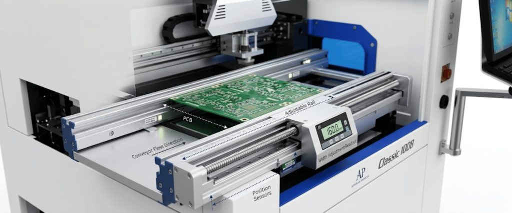
3) Configure the PCB Conveyor Rail
The conveyor rail must be adjusted to match the width of your PCB.
Input the PCB width into the machine software; most automatic printers will auto-adjust the rail width
Load a test PCB into the rail and confirm it travels smoothly from the entrance to the stop cylinder without jamming or wobbling.
Verify that the PCB surface height aligns with the rail platform, and use support pins to correct any height inconsistency.
Check that the entrance and exit clearances are smooth; re-adjust rail width if the board is too tight or too loose.
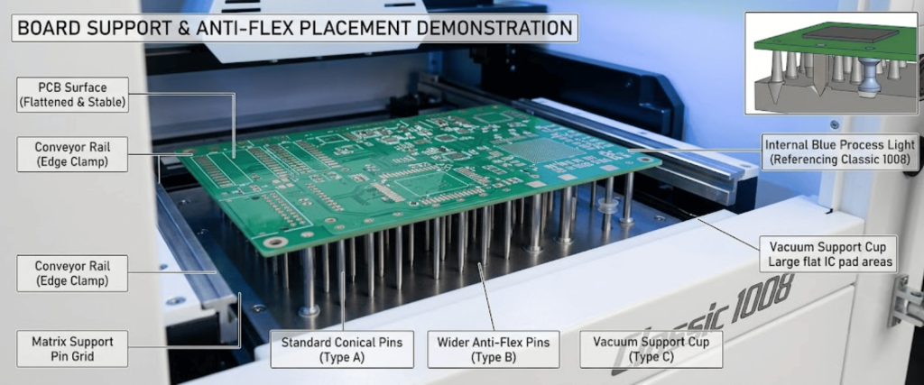
4) Place Support Pins (Thimbles)
Support pins hold the PCB flat from below during printing. Incorrect pin placement causes board flex, which directly causes paste smearing and misalignment.
Follow these guidelines
Position chip-type pins perpendicular to the squeegee travel direction, or at no more than 45°.
Place cylindrical pins evenly across the board’s underside.
Add dedicated pins beneath high-density components like BGA and QFN pads to ensure the squeegee applies even pressure across the full print area.
After placing, gently press each pin by hand to confirm it is stable and will not shift during printing.
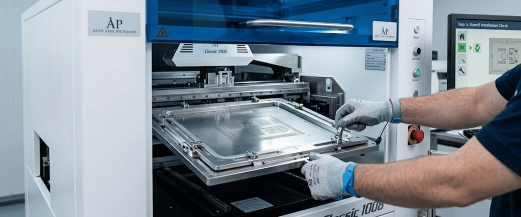
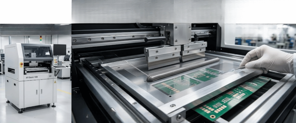
5) Install the Stencil
Unlock the stencil holder and adjust its width to match the stencil frame size.
Place the stencil on the work table aligned with the conveyor belt direction.
Push the stencil frame to the stop cylinder and confirm it is fully seated.
Lock the stencil using pneumatic clamps or manual fasteners, and confirm that it does not wobble.
Raise the Z-axis so the stencil lowers toward the PCB and visually confirm the stencil apertures are roughly over the correct pad areas before proceeding to alignment.
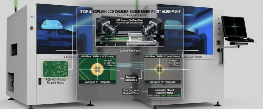
6) Set Mark Points (Fiducial Alignment)
This is one of the most critical steps. The vision system uses fiducial marks on both the PCB and the stencil to calculate and correct any offset between them.
Select two diagonal fiducial marks on the PCB; they should be clearly visible, symmetrical, and free of any interference in the surrounding area.
Use the CCD camera in the software to locate and confirm each fiducial; adjust camera brightness and contrast until the marks are auto-detected reliably.
Repeat the same process to identify and register fiducials on the stencil.
Run a fine alignment pass, and the machine will calculate X, Y, and theta (rotational) offsets and correct for them automatically.
Verify that pad-to-aperture alignment is within ≤ 0.02mm before proceeding.
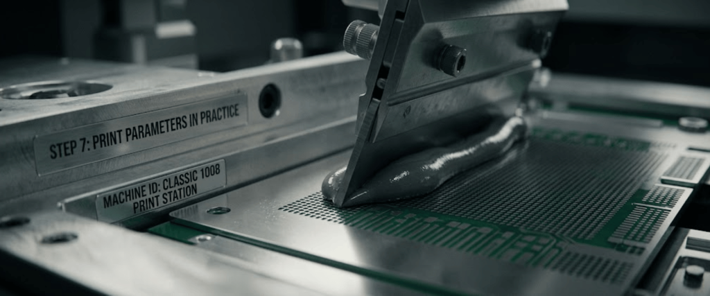
7) Set Squeegee and Printing Parameters
Configure these parameters in the software before running your first print.
Squeegee pressure: Typically 3–5 kg depending on stencil thickness and paste viscosity; too high wears the stencil and blade, too low causes insufficient paste volume.
Print speed: 50–80 mm/s for standard boards; slower speeds for fine-pitch components.
Squeegee angle: Maintain 65° for optimal paste transfer.
Separation speed: 0.5–1.5 mm/s for controlled stencil lift-off; too fast causes paste peaks and bridging
Separation distance: Typically 1–2 mm lift before the board is fully released from the stencil.
Squeegee stroke: Set the start and end positions so the blade begins and ends 30mm beyond the stencil print area.
8) Add Solder Paste and Run First Print
Apply solder paste across the stencil in a bead, approximately 1 cm high, 1.5–2 cm wide, and 3 cm longer than the print area on each side.
Load a test PCB (use a film/dummy board first if available) and initiate a trial print run.
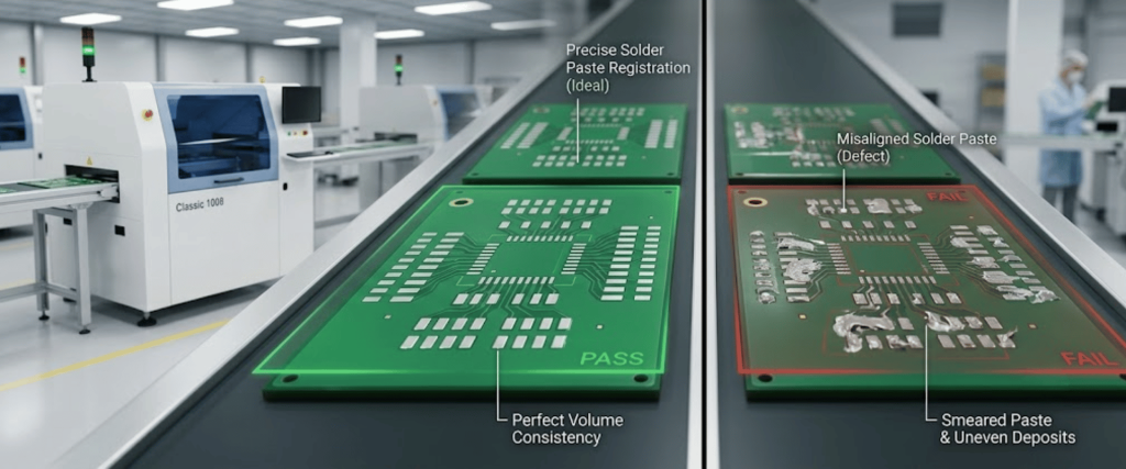
After printing, inspect the first board under a microscope or SPI (Solder Paste Inspection) system, check for complete fill, sharp edges, correct volume, and no bridging between pads.
If misalignment is found, use the X, Y1, and Y2 offset controls to correct incrementally.
Once the first print passes inspection, lock in the parameters, save the program, and run 5 boards to confirm stability before moving to full production.
9) Stencil Cleaning and Ongoing Monitoring
Set the printer’s auto-clean cycle for every 5–10 boards, depending on paste type and stencil aperture density. During production.
Inspect paste volume and alignment every 30 boards.
Replace paste on the stencil every 2 hours or when the bead drops usable height.
Monitor for paste drying at stencil edges, use the wet wipe cycle with IPA to maintain aperture cleanliness.
Key SMT Stencil Printer Parameters at a Glance
Parameter
Recommended Range
Impact of Getting It Wrong
Squeegee Pressure
3–5 kg
Too high: stencil wear, paste smearing. Too low: voids, insufficient paste.
Print Speed
50–80 mm/s
Too fast: incomplete fill. Too slow: paste, drag, or smearing.
Squeegee Angle
65°
Deviations reduce paste transfer efficiency.
Separation Speed
0.5–1.5 mm/s
Too fast: paste peaks and bridging. Too slow: slows cycle time.
Alignment Offset
≤ 0.02 mm
Exceeding this causes tombstoning, bridging, or short circuits.
Stencil Cleaning Interval
Every 5–10 boards
Skipping causes blocked apertures and inconsistent deposits.
Common Setup Mistakes to Avoid
Skipping support pin placement, even minor board flex under the squeegee, causes uneven paste and pad misalignment.
Running paste at the wrong temperature, cold paste straight from the fridge, increases viscosity and causes voids; always warm to room temperature first.
Not locking the stencil properly, a stencil that shifts mid-run, contaminates the entire batch.
Setting the squeegee stroke too short, the blade should extend 30mm past the print area on both sides to maintain consistent pressure through the full print pass.
Skipping the first-piece microscope inspection, problems invisible to the eye become clear under magnification; confirm before batch production.
Conclusion
Setting up an automatic SMT stencil printer correctly is not complicated, but it is precise.
Each step, from PCB support pins to fiducial alignment and squeegee pressure, directly affects paste deposit quality. A sloppy setup leads to defects that only appear after reflow, costing you rework time and material.
Follow this guide methodically for each new PCB program, save your confirmed parameters, and the machine will deliver consistent, high-quality results across your entire production run.
An automatic stencil printer is one of the best investments in any SMT line, but only when set up properly.
Frequently Asked Questions (FAQs)
1. What is the correct squeegee angle for an automatic SMT stencil printer?
The standard squeegee angle is 65°. This angle provides optimal solder paste transfer through the stencil apertures and is supported across most automatic printer platforms.
2. How often should the stencil be cleaned during production?
Most production lines run a stencil underside cleaning cycle every 5–10 boards. For fine-pitch boards with tight aperture spacing, cleaning every 5 boards is recommended to prevent aperture clogging.
3. What happens if the solder paste alignment is off after setup?
Use the X, Y1, and Y2 offset adjustment controls in the software to fine-tune alignment incrementally. Alignment offset should be kept within ≤ 0.02mm to prevent defects like bridging, tombstoning, or insufficient solder.
4. How long can solder paste stay on the stencil before it needs to be replenished?
Solder paste on the stencil should be replenished approximately every 2 hours. From the time paste is printed onto a PCB to the point it enters the reflow oven, the maximum allowable time is 4 hours.
5. Do I need to bake PCBs before printing?
For boards that have been stored and may have absorbed moisture, baking at around 100°C for 2–3 minutes before printing is recommended to avoid soldering defects caused by moisture content in the substrate.
6. Can one automatic stencil printer program work for multiple PCB designs?
No. Each PCB design requires its own saved program with specific dimensions, fiducial locations, support pin configurations, and printing parameters. Mixing programs between board designs will cause misalignment and defects.
Since 1992, Applied Physics Corporation has been a leading global provider of precision contamination control and metrology standards. We specialize in airflow visualization, particle size standards, and cleanroom decontamination solutions for critical environments.